In the previous section, we looked at modelling propagation delay using the after keyword. The emphasis on after is an important one:
the
afterkeyword is ignored by synthesis tools. Real delays are an intrinsic property of internal electronics and routing.
Stability
Consider the D-Type latch, a 1-bit memory and a basic building block of synchronous digital systems.
This is a device with two primary inputs, and at least one output:
- Input D
- Latch enable input LE
- Output Q
The input D is ignored unless the level of the LE pin is HIGH, in which case the output Q=D. When LE is reset to a LOW state, the last stable output Q is held stable (remembered) and the input D is ignored once more. For deterministic behaviour, the D input needs to be stable (constant) before and sometimes after a change in the LE input.
- The set-up time is the period for which D must be stable before LE changes
- The hold time is the period for which D must be stable after LE changes
A failure to honour the set-up or hold time will result in a period of unpredictable changes in the Q output for an unspecific period of time. In the case where LE is falling, a change in D might not be registered in the output Q.
As we will see, the situation is even more serious in synchronous logic.
This description can be confusing, and to some extent, is also incomplete. It is probably easier to illustrate the behaviour of a D-Latch through modelling in VHDL, and through testing.
The D-Latch in VHDL
The VHDL for a D-Latch primitive is as follows:
library ieee;
use ieee.std_logic_1164.all;
--use ieee.std_logic_unsigned.all;

-- Component 1 - very simple device that performs a logical OR on three single bit inputs
entity dlatch_primative is
port(  	D:	in std_logic;
	LE:	in std_logic;
	Q:	out std_logic
);
end dlatch_primative;

--This component has two architecture
architecture v1 of dlatch_primative is
begin
	process(D,LE)
	begin
		if (LE='1') then
			Q <= D after 5 ns;
		end if;
		-- The absence of an else will result in a latching behviour
	end process;
end v1;
If you examine the three highlighted lines, these are central to the latch behaviour. You can hopefully see how simple a latch really is – if the LE signal is HIGH, then the output = input. However, what if the LE signal is LOW, and where the latching behaviour specified? The answer is that the latching behaviour it is implicit. The IF statement only specifies what happens when LE='1'. For all other values of LE, nothing is specified, so the compiler assumes the signal Q is latched for all other values of LE. When a conditional statement does not provide full coverage, we get implicit latching behaviour.
Also note the sensitivity list for the process block.
The process block will only update if one or more of the signals in the sensitivity list changes
The output may need updating for a change in either D or LE (or both). Therefore both are listed. It is essential that you list these correctly otherwise you might have different (and often unexpected) behaviour. Incorrectly specifying the sensitivity list is a common error and is sometimes hard to spot.
Testing the D-Latch
To illustrate the D-Latch, a simple test bench is included below.
library ieee;
use ieee.std_logic_1164.all;
use ieee.numeric_std.all;
--use ieee.std_logic_unsigned.all;
--use std.textio.all;

entity dlatch_test is
end dlatch_test;

architecture v1 of dlatch_test is
	--Declare signals
	signal D_INPUT     : std_logic;
	signal LATCH_INPUT : std_logic;
	signal Q_OUTPUT    : std_logic;
	constant T         : time  := 50 ns;

begin
	--Instantiate v1 of the component type dlatch_primative
	u1: entity work.dlatch_primative(v1) PORT MAP (
		D  => D_INPUT,
		LE => LATCH_INPUT,
		Q  => Q_OUTPUT
	);

	main_process:
	process
		--Declarations here
	begin
		--Start with a wait to illustrate a point
		wait for T;

		--Initialise
		D_INPUT     <= '0';
		LATCH_INPUT <= '0';
		wait for T;

		--Let's go
		D_INPUT     <= '1';
		LATCH_INPUT <= '0';
		wait for T;

		D_INPUT     <= '1';
		LATCH_INPUT <= '1';
		wait for T;

		D_INPUT     <= '0';
		LATCH_INPUT <= '1';
		wait for T;

		D_INPUT     <= '1';
		LATCH_INPUT <= '1';
		wait for T;

		D_INPUT     <= '1';
		LATCH_INPUT <= '0';
		wait for T;

		D_INPUT     <= '0';
		LATCH_INPUT <= '0';
		wait for T;

		D_INPUT     <= '1';
		LATCH_INPUT <= '0';
		wait for T;

		D_INPUT     <= '0';
		LATCH_INPUT <= '0';
		wait for T;

		D_INPUT     <= '0';
		LATCH_INPUT <= '1';
		wait for T;

		D_INPUT     <= '0';
		LATCH_INPUT <= '0';
		wait for T;

		D_INPUT     <= '1';
		LATCH_INPUT <= '0';
		wait for T;

		D_INPUT     <= '0';
		LATCH_INPUT <= '0';
		wait for T;

		--End of test is to wait forever
		wait;
	end process;

end v1;
This somewhat verbose and manual approach is fine for small examples such as this. The output for this is shown in the following ModelSim waveform.
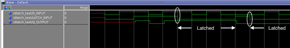
From this, again we can observe the behaviour of the D-Latch under different conditions.
- At the start, we see red traces. In ModelSim, this means the signals are uninitialized (‘U’). This was done on purpose to make this point as uninitialized signals can be a source of serious bugs. This is something you might not spot had you tested this in hardware.
- Once the LATCH_INPUT (connected to LE) is asserted high, the output is assigned to the input (HIGH). As long as the level of the latch enable is high, so the output follows the input. As soon as the latch enable falls low, so the last stable output is latched and the input is ignored. This is observed in the first latching phase.
Already, you might be thinking that sequential logic is more challenging to exhaustively test, and you would be right. It is not enough to consider all input combinations, but also all possible sequences to qualify for exhaustive testing. The following sequences are covered:
- uninitialized inputs
- inputs changing with LE LOW (no change in output)
- inputs changing with LE HIGH (change in output)
- latching a logic HIGH
- latching a logic LOW
But there is more! What about set up and hold time? This is not covered here, so we need to expand the test to check for this. I will assume the set up time to be 5ns and the hold time to be 1ns.
Checking set up time
Look at the following VHDL for a modified D-Latch. For brevity, I’ve only included the architecture.
architecture v1 of dlatch_primative is
	constant T_setup : time := 5 ns;
	constant T_hold  : time := 1 ns;
begin
	process(D,LE)
	begin
		--Check for setup violation
		if LE'EVENT then
			assert (D'LAST_EVENT >= T_setup)
				report "Setup time violated"
				severity error;
		end if;
		--The core logic
		if (LE='1') then
			Q <= D after 5 ns;
		end if;
		-- The absence of an else will result in a latching behviour
	end process;
end v1;
You will notice some additional code (highlighted).
LE'EVENTreturns a boolean which is true if the LE signal has changedD'LAST_EVENTreturns the time since the D signal last changed
These are both examples of signal attributes. The syntax is SIGNAL’ATTRIBUTE.
Reading the logic now, the new code checks to see if the LE signal has changed. If so, it then looks at how long it has been since the D input signal changed. If this is greater than or equal to the set up time, no action is taken, otherwise an error is written to the console output (below).
The new tests added the test bench check the edge case (the limit where the test should pass) and a failure condition to check the assert statement detects the error.
--Edge case
D_INPUT     <= '1';
wait for 5 ns;
LATCH_INPUT <= '1';
wait for T;
LATCH_INPUT <= '0';
wait for T;

--Failure case
D_INPUT     <= '0';
wait for 4 ns;
LATCH_INPUT <= '1';
wait for T;
LATCH_INPUT <= '0';
wait for T;
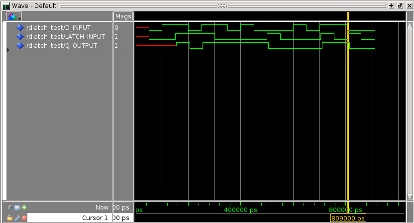
The output from the simulation is as follows:
run -all
# ** Error: Setup time violated
#    Time: 50 ns  Iteration: 1  Instance: /dlatch_test/u1
# ** Error: Setup time violated
#    Time: 809 ns  Iteration: 1  Instance: /dlatch_test/u1
Note that there are two violations of the set up time, although only one test was added.
- The first is at 50ns, when the LATCH_INPUT and D_INPUT signals change from ‘U’ to ‘0’.
- The second refers to the explicit test added to the end of the test bench (marked by the yellow cursor)
The first may have surprised you, but again, this is the power of simulation. The initial value of either input, in the absence of power-on reset, are undefined.Therefore a transition from ‘U’ to ‘0’ could indeed be a ‘1’ to ‘0’ in a real system.
What is missing are tests around the LE falling. I will leave the reader to implement those.
Checking hold time
The hold time can be checked in a similar way.
--Check for hold violation
if D'EVENT then
	assert (LE'LAST_EVENT >= T_hold)
		report "Hold time violated"
		severity error;
end if;
Again, we add an edge case test and a failure to the test bench:
--Edge case
LATCH_INPUT <= '1';
wait for 1 ns;
D_INPUT <= '1';
wait for T;

--failure case
LATCH_INPUT <= '0';
wait for T;
LATCH_INPUT <= '1';
wait for 500 ps;
D_INPUT <= '0';
wait for T;
Again we see two errors:
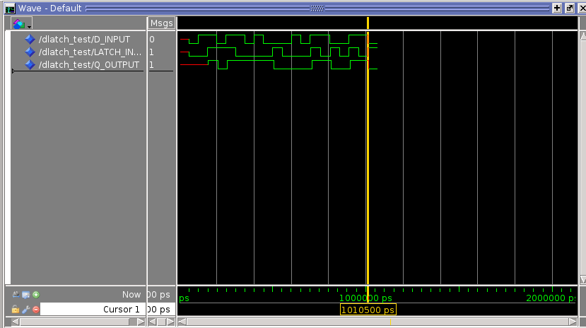
run -all
# ** Error: Setup time violated
#    Time: 50 ns  Iteration: 1  Instance: /dlatch_test/u1
# ** Error: Hold time violated
#    Time: 50 ns  Iteration: 1  Instance: /dlatch_test/u1
# ** Error: Setup time violated
#    Time: 809 ns  Iteration: 1  Instance: /dlatch_test/u1
# ** Error: Hold time violated
#    Time: 1010500 ps  Iteration: 1  Instance: /dlatch_test/u1
The Waveform output in ModelSim is shown below, with the yellow cursor marking the time of the second hold-time violation.