Introduction
Intel Quartus (Standard Edition) provides a set of reusable library components to help you be more productive. One such component is the scfifo, a ram based first-in-first-out buffer that can be used for buffering real-time streams of data.
The operation is a storage array of samples (typically ram) where data can added, and can only be read out in the order it was written in. Hence the name First In First Out (FIFO).
One of the applications is for real-time systems with strict timing constraints.
An FPGA is highly suited to hard-real-time tasks such as sampling or control. An FPGA allows true concurrently where tasks are divided spatially (as opposed to temporally on a CPU core). Instead of time-slicing (the basis of multi-tasking on a CPU core), the FPGA can simply add / replicate hardware to achieve true concurrency.
Often we need to interface a hard-real-time system with a softer one. For example, if an FPGA is to perform the hard-real-time task of sampling an analog signal (via an ADC), the data can be buffered until such time that a CPU is ready to receive and process it. Without a guaranteed place to store data in real-time, data will be lost. The role of buffering can be performed by a FIFO.
As long as the throughput is greater than the data rate, and buffering is sufficiently deep, then (FIFO) buffering relaxes the timing requirements of the softer-real-time system (e.g. a CPU) and prevents data loss.
An analogy is the process of eating – humans don’t tend to graze on food in the way cows do – instead they follow cycles of fasting for a few hours and controlled binging (meal times)**.
(**ok, when I was a teenager, I may have behaved more like the cow..analogies are rarely watertight 😉
So the CPU is the same – often we perform context switches in software, attending to multiple devices and tasks in a given time. When it’s the turn of the sampling process, it can pull down all the available (buffered) data in one batch and perform what ever tasks are required – as long as the sampling buffer never becomes full.
So some key features of a FIFO buffer is:
- One device can write to the buffer while another reads
- We can control the depth (in words) and width (in bits) of the buffer
- We know how many samples are in the buffer
- We can detect when the buffer is full or empty (one of which is usually a critical event).
The single clock FIFO (scfifo) meets all these requirements and more. Before we look at the specifics of this device, let’s consider some scenarios where it might be used.
Data source as a hard real-time producer
If the hard-real-time system is a data source (aka producer), then the buffer provides an immediate location to store data as it is produced (otherwise will be lost). The data sink (aka consumer) can read batches of data when it has capacity to do so. As long as the buffer never gets full, this guarantees no data is lost.
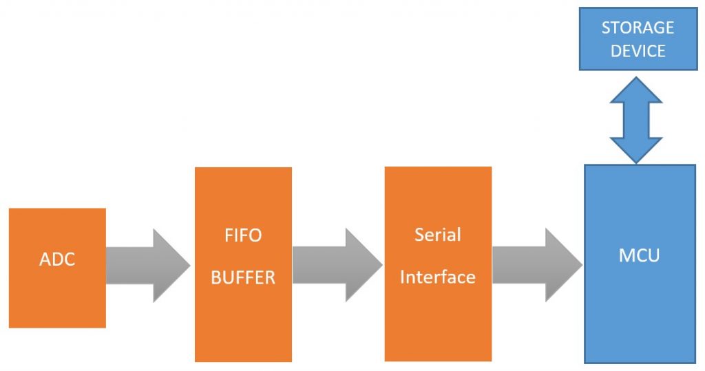
An example (depicted above) would be a system that samples data (ADC) at a fixed rate, stores them in memory, performs a some analysis and saves the results to persistent storage. Some key points to note:
- The ADC will perform a conversion on very precise intervals (driven by a crystal oscillator clock). It has the tightest timing constraints in the system, so is performed by the FPGA (in orange).
- The ADC can write it’s data into a FIFO without having to wait
- The MCU will request data via a serial interface (SPI or I2C are common) typically in bursts. The timing constraint is simply that the FIFO must never get filled. We say it’s timing constraints are much more relaxed / it has greater timing slack.
- The load on the CPU is very uneven.
- Firstly, enough data needs to be captured in an array.
- Once enough samples are acquired, it performs some analysis (can be computationally expensive)
- Finally, the results need to be written to persistent storage (usually much slower than the CPU).
- While all of this is happening, data is still being sampled on strict time intervals.
There are numerous solutions to this of course.
The key point is that the FIFO buffer gives the MCU the timing slack it needs to attend to other tasks. When it comes back to reading data, “it can play catch up”. By relaxing the timing constraints put on the microcontroller, we simplify the design of the software.
Data sink as a hard real-time consumer
When the hard-real-time system is a sink (a consumer of data), we probably mean that it must be provided data with tight timing criteria and should never be starved of data. One example you might have already met is an optical disc writer – once started, if the optical drive is starved of data even once during the write process, the disk can be rendered useless. The producer in this case is often a software package running on a general purpose operating system (not a real time system).
Another example is watching streamed video. Your brain expects video to be played back in real time, otherwise the motion will stall / speed up and the whole illusion of animation is disturbed. In the data originated from the Internet, which is notorious for changes in data transmission rates, then buffering is usually required to maintain a constant framerate. A common strategy is to pre-fill the buffer at the start (have you ever seen the words “buffering” appear?) and try to keep the buffer at full capacity.
The task of the producer is to keep the buffer as full as possible and never starve the consumer by allowing the buffer to become empty.
Consider the example of a Digital to Analogue Converter (DAC) playing audio that is streamed across a network.
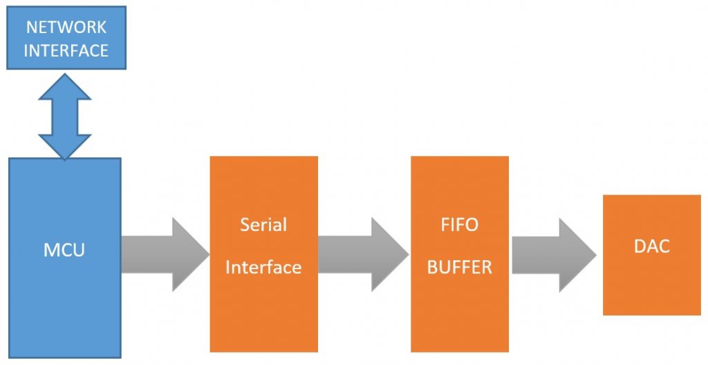
We note the following key points:
- The DAC must be able to convert the next sample at a fixed and determined rate. If it is starved of data, the audio will stall and sound incorrect. Broken audio through dropped samples is one of the indices for quantifying quality of service (QoS).
- In the source of the data is the Internet, then the incoming birate is highly likely to be variable. The average bitrate must be greater than or equal to that of the DAC and the buffer deep enough to cope with any length of network dropout.
- The MCU loading is likely to be uneven as it has at least two devices to communicate with (network interface and the serial interface), and possibly other tasks as well.
- By pre-filling the FIFO buffer with samples, and making every effort to keep it full, the DAC will hopefully never be starved of data. Note that this introduces a delay into the audio channel (more a problem for VoIP systems than an Internet radio).
Once again, by employing a buffering strategy, we are giving back timing slack to the MCU.
What about multitasking?
Single core CPUs are sequential machines, so technically only perfom one task at a time. Multitasking on a single core CPU is based on rapid or responsive task switching (also known as preemption) which is a topic in it’s own right. Like the rapidly changing frames that create the illusion of movement in a movie, so multitasking is often an illusion. Furthermore, designing robust multi-tasking software takes skill, care and effort to manage real-time data, and comes with overheads and additional complexity. If there were multiple hard-real-time devices to manage, this could get very problematic (only one can be the highest priority to a CPU). The reality is both real-time software techniques and buffering are often used, especially where network interfaces are involved (they can block from anywhere between a few ms and several hours!).
The Intel SCFIFO
We are now going to take a closer look at library component for buffering on an Intel/Altera FPGA. The documentation from Intel can be found here and is fairly comprehensive. However, to best understand / confirm our understanding of a component, it is always good to try it for yourself. A good way to do this is to write a testbench to try out different scenarios including edge-cases.
There are two approaches discussed here
- The first method writes tests as sequential VHDL code and can be found here
- The second method refines this by using a look-up table, and can be found here
All the testing was performed using ModelSim (Altera Standard Edition)
Creating the testbench
I first created a file fifo_test.vhd
The skeletal structure of this file is as follows:
library ieee;
use ieee.std_logic_1164.all;

LIBRARY altera_mf;
USE altera_mf.altera_mf_components.all;

entity fifo_test is
end fifo_test;

architecture rtl of fifo_test is
begin
end rtl;
Note the library declaration (highlighted). This is required to use the Intel Megafunctions.
As is always the case with a testbench, the entity is entirely empty.
Declaring the SCFIFO component
Next, we need to tell the compiler about the entity of the component we wish to test. Luckily this can be found inside the file altera_mf_components.vhd which can be found in the sub-folder
[quartus home]\quartus\libraries\vhdl\altera_mf
For my machine, this was
C:\intelFPGA\16.1\quartus\libraries\vhdl\altera_mf\altera_mf_components.vhd
Search inside this file for scfifo and you will find the component declaration that you need. Copy and paste this into your architecture (before the begin statement). You may wish to edit some of the default generic values. I am using a Cyclone IV for all my examples, so I’ve changed the default value of intended_device_family to “Cyclone IV”. ModelSim requires this to be set for correct simulation (failure to set it generates an error at simulation time).
architecture rtl of fifo_test is
	--Component declaration
	component scfifo
		generic (
			add_ram_output_register	:	string := "OFF";
			allow_rwcycle_when_full	:	string := "OFF";
			almost_empty_value	:	natural := 0;
			almost_full_value	:	natural := 0;
			intended_device_family	:	string := "Cyclone IV";
			enable_ecc		:	string := "FALSE";
			lpm_numwords		:	natural;
			lpm_showahead		:	string := "OFF";
			lpm_width		:	natural;
			lpm_widthu		:	natural := 1;
			overflow_checking	:	string := "ON";
			ram_block_type		:	string := "AUTO";
			underflow_checking	:	string := "ON";
			use_eab		:	string := "ON";
			lpm_hint		:	string := "UNUSED";
			lpm_type		:	string := "scfifo"
		);
		port(
			aclr		:	in std_logic := '0';
			almost_empty	:	out std_logic;
			almost_full	:	out std_logic;
			clock		:	in std_logic;
			data		:	in std_logic_vector(lpm_width-1 downto 0);
			eccstatus	:	out std_logic_vector(1 downto 0);
			empty		:	out std_logic;
			full		:	out std_logic;
			q		:	out std_logic_vector(lpm_width-1 downto 0);
			rdreq		:	in std_logic;
			sclr		:	in std_logic := '0';
			usedw		:	out std_logic_vector(lpm_widthu-1 downto 0);
			wrreq		:	in std_logic
		);
	end component;
begin

end rtl;
Below the component declaration we need to add some internal signals.
	-- internal signals
	signal aclr		:	std_logic := '0';
	signal almost_empty	:	std_logic;
	signal almost_full	:	std_logic;
	signal clock		:	std_logic;
	signal data		:	std_logic_vector(7 downto 0);
	signal eccstatus	:	std_logic_vector(1 downto 0);
	signal empty		:	std_logic;
	signal full		:	std_logic;
	signal q		:	std_logic_vector(7 downto 0);
	signal rdreq		:	std_logic;
	signal sclr		:	std_logic := '0';
	signal usedw		:	std_logic_vector(2 downto 0);
	signal wrreq		:	std_logic;
As will seen, these will eventually be connected to the fifo component inputs and outputs.
Your architecture should resemble the listing below.
architecture rtl of fifo_test is
	--Component declaration
	component scfifo
		generic (
			add_ram_output_register	:	string := "OFF";
			allow_rwcycle_when_full	:	string := "OFF";
			almost_empty_value	:	natural := 0;
			almost_full_value	:	natural := 0;
			intended_device_family	:	string := "Cyclone IV";
			enable_ecc		:	string := "FALSE";
			lpm_numwords		:	natural;
			lpm_showahead		:	string := "OFF";
			lpm_width		:	natural;
			lpm_widthu		:	natural := 1;
			overflow_checking	:	string := "ON";
			ram_block_type		:	string := "AUTO";
			underflow_checking	:	string := "ON";
			use_eab		:	string := "ON";
			lpm_hint		:	string := "UNUSED";
			lpm_type		:	string := "scfifo"
		);
		port(
			aclr		:	in std_logic := '0';
			almost_empty	:	out std_logic;
			almost_full	:	out std_logic;
			clock		:	in std_logic;
			data		:	in std_logic_vector(lpm_width-1 downto 0);
			eccstatus	:	out std_logic_vector(1 downto 0);
			empty		:	out std_logic;
			full		:	out std_logic;
			q		:	out std_logic_vector(lpm_width-1 downto 0);
			rdreq		:	in std_logic;
			sclr		:	in std_logic := '0';
			usedw		:	out std_logic_vector(lpm_widthu-1 downto 0);
			wrreq		:	in std_logic
		);
	end component;

	-- internal signals
	signal aclr		:	std_logic := '0';
	signal almost_empty	:	std_logic;
	signal almost_full	:	std_logic;
	signal clock		:	std_logic;
	signal data		:	std_logic_vector(7 downto 0);
	signal eccstatus	:	std_logic_vector(1 downto 0);
	signal empty		:	std_logic;
	signal full		:	std_logic;
	signal q		:	std_logic_vector(7 downto 0);
	signal rdreq		:	std_logic;
	signal sclr		:	std_logic := '0';
	signal usedw		:	std_logic_vector(2 downto 0);
	signal wrreq		:	std_logic;

begin

end rtl;
Lines 40-52 are the internal signals and it is these we will be using for testing. Note there is a signal for every input/output port in the component under test.
Instantiating a fifo
Now the compiler knows about the device, including any generics, inputs and outputs, so we can now instantiate any number of these fifo components in our testbench. You can think of this as equivalent to placing a component on a schematic. Each component that you place is a unique instance (consuming logic gates) with it’s own inputs, outputs and generic properties. I am only going to instantiate one instance for the purposes of this exercise. You do this after the begin statement.
The general form is as follows:
<instance_name> : <component_name>
	generic map
	(
		<name> => <value>,
		...
	)
	port map
	(
		<formal_input> => <expression>,
		<formal_output> => <signal>,
		<formal_inout> => <signal>,
		...
	);
Instance name is the identifier for each instance. In a schematic you would conventionally write U1 for component 1, U2 for component 2 etc.. In this example, I’ve simply called the instance fifo. The component name is scfifo which must be the same as the component entity name.
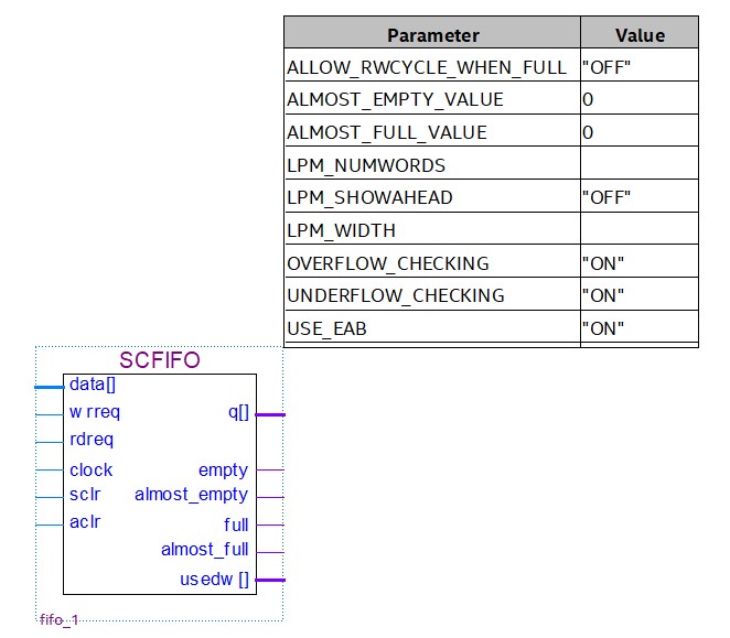
For the scfifo, I used the following:
begin

--instantiate a scfifo
fifo : scfifo
	generic map
	(
			almost_empty_value	=> 2,
			almost_full_value	=> 6,
			lpm_numwords		=> 8,
			lpm_showahead		=> "OFF",
			lpm_width		=> 8,
			lpm_widthu		=> 3,
			overflow_checking	=> "ON",
			underflow_checking	=> "ON",
			use_eab		=> "ON"
	)
	port map
	(
			aclr		=> aclr,
			almost_empty 	=> almost_empty,
			almost_full	=> almost_full,
			clock		=> clock,
			data		=> data,
			eccstatus	=> eccstatus,
			empty		=> empty,
			full		=> full,
			q		=> q,
			rdreq		=> rdreq,
			sclr		=> sclr,
			usedw		=> usedw,
			wrreq		=> wrreq
	);
Setting the generic values
Note how the generics are set (or overridden where defaults are given). Let’s look at some of the most important generic values:
First we specify how many words will be held in this fifo by setting lpm_numwords => 8
All words stored in the fifo buffer have a fixed and equal width. For this example 8 bits are used (each is a byte) although other values are possible. The word size (in bits) is specified using lpm_width => 8
The output usedw is a binary output that indicates how many storage words have been used. You need to specify how many bits are needed to represent this. We calculate this a  (represents 0..
 , that is 0..7).
Therefore, we specify lpm_widthu => 3
What if you have 8 (binary 1000) samples in the fifo buffer? In that case, usedw=0 and the full output bit is set high. You therefore use full as the most significant bit.
As already suggested, an important feature of the fifo is that it can indicate when the fifo is empty or full. From the documentation, it is stated that you should not attempt to add more data to a full fifo or try to to read data when it is empty. If there is a possibility of this happening in your system, you can either implement the protection logic yourself or (probably better), you can have it added for you by including the following two lines (although these are the defaults)
overflow_checking => "ON",
underflow_checking => "ON",
Another view on this is that you have the option to turn this off and thus save some logic in the event it is not required.
If we want to use on-chip ram for storing the buffered values, then we can specify this as follows
use_eab => "ON"
Again this is the default, but it’s sometimes helpful to specify things explicitly to make the code more readable. Finally, it might be useful to know when the buffer is close to full or empty
almost_empty_value => 2
almost_full_value => 6,
- The
almost_emptyoutput is asserted when
- The
almost_fulloutput is asserted when
We are not going to be using this here, but it’s interesting to observe the behavior.
Assigning Test Signals
Note in the port map section, each port signal is connected to an internal signal of the same name. The generic form is:
port map  port map  (
    <formal_input> => <expression>,
    <formal_output> => <signal>,
    <formal_inout> => <signal>,
    ... );
The formal_input, formal_output and formal_inout are the port names taken from the entity. They can connect to any signal of the right type, but it is common to create and connect to signals of the same name. If you look closely at the listings above, you will see that component inputs and outputs are connected to internal signals of the same name. If you added more component, you may add more internal signals and break this convention.
Writing the tests
Finally, we get to the point where we write some tests. The core principles of benchmark testing are as follows:
- Assert the internal signals that are connected to the component inputs
- Wait for the component to update (1ps would work, but I’ve chosen to use the next falling edge of the clock)
- Observe and check the internal signals that are connected to the component outputs with the
assertfunction.
We typically write testbench code as a series of sequential statements, where the order does matter. Therefore, we almost always write testbench code within one or more process blocks. This example will use two process blocks: one for the clock generation and another for implement the tests. As we will see, this lends itself to an efficient way to build up and keep track of test sequences.
clock generation
A critical input signal is the clock. It is common to generate this in a separate process block for reasons (I hope) will become apparent:
--Generate the clock
clk:	process
	begin
		clock <= '0';
		wait for 10 ns;
		for n in 1 to 64 loop
			clock <= '1';
			wait for 10 ns;
			clock <= '0';
			wait for 10 ns;
		end loop;

		wait;
	end process;
Note the following:
- The process block has no sensitivity list.
- instead of a sensitivity list, it uses
wait forto wait for a specified amount of simulation time to elapse - there is a single
waitat the end (without which the simulator will struggle to know when to stop).
Note that the clock signal is declared in the testbench architecture, and is connected (via port map) to the clock input of the fifo.
Specific tests
Now we have a clock signal, we can write a separate process block to generate tests that are synchronized with the clock signal. Remember that each process block is essentially concurrent (think of them as separate hardware components in a schematic).
The tests are written in a second process block. Let’s look at a few examples:
Default output (after reset)
The very first simple check the default value in the output before any read or write
		data <= "00000000";
		rdreq <= '0';
		wrreq <= '0';
		wait until falling_edge(clock);
		assert usedw = "000"  report "Wrong number of samples" severity error;
		assert q = "00000000" report "Wrong output"            severity error;
		assert empty = '1' report "Empty bit unexpected"       severity error;
		assert full  = '0' report "Full bit unexpected"        severity error;
Note the empty bit is checked (it should be a ‘1’ for an empty buffer).
Add the first word
In this test, the wrreq line is asserted (line 4) with some data presented at the input.
		--Add a word
		data <= "00000011";
		rdreq <= '0';
		wrreq <= '1';
		wait until rising_edge(clock);
		wait until falling_edge(clock);
		assert usedw = "001"  report "Wrong number of samples" severity error;
		assert q = "00000000" report "Wrong output"            severity error;
		assert empty = '0' report "Empty bit unexpected"       severity error;
		assert full  = '0' report "Full bit unexpected"        severity error;
In line 7 we check the usedw output reflects the number of words (1) used in the buffer. Note that the empty bit is no longer ‘0’.
Edge Case : simultaneous read and write to a full buffer
If you read the complete source, you will see a number of additional tests. I’ve skipped over many of these so I can highlight some points of interest. In this test, we attempt to add a sample to an already full buffer, followed by an attempt to both read and write.
		--Add a word (should be dropped)
		data <= "00000000";
		rdreq <= '0';
		wrreq <= '1';
		wait until rising_edge(clock);
		wait until falling_edge(clock);
		assert usedw = "000"  report "Wrong number of samples" severity error;
		assert q = "11111111" report "Wrong output"            severity error;
		assert empty = '0' report "Empty bit unexpected"       severity error;
		assert full  = '1' report "Full bit unexpected"        severity error;


		--Add and read a word on a full fifo (edge case - write fails then read succeeds)
		data <= "11110000";
		rdreq <= '1';
		wrreq <= '1';
		wait until rising_edge(clock);
		wait until falling_edge(clock);
		assert usedw = "111"  report "edge: Wrong number of samples" severity error;
		assert q = "10101010" report "edge: Wrong output"            severity error;
		assert empty = '0' report "Edge: mpty bit unexpected"       severity error;
		assert full  = '0' report "Edge: Full bit unexpected"        severity error;
As you might except, an attempt to write a value to a full buffer has no effect and the sample is simply lost.
What is less obvious is the behavior when you try to both read and write to a full buffer.
Q. Is the read performed first so the write can succeed?
This test revealed that in this scenario, the write will fail and the read will succeed, leaving a buffer with 7 samples (from a maximum of 8).
You might have expected a different result. However, to create a fifo that first free’s up space (the read) so the simultaneous write can succeed would require addition logic and possibly wait states. You could always implement that yourself of course.
The important thing is that we understand the behavior for the edge cases and don’t make assumptions.
Let’s look at similar edge case.
Edge Case : simultaneous read and write to an empty buffer
		data <= "11110000";
		rdreq <= '1';
		wrreq <= '1';
		wait until rising_edge(clock);
		wait until falling_edge(clock);
		assert usedw = "001"  report "edge: Wrong number of samples" severity error;
		assert q = "10101010" report "edge: Wrong output"            severity error;
		assert empty = '0' report "Edge: Empty bit unexpected"       severity error;
		assert full  = '0' report "Edge: Full bit unexpected"        severity error;
As with the full buffer, a simultaneous read and write partially fails for the case where the buffer is empty. The read will fail and the write will succeed, resulting in a buffer with one sample. From this and other tests, it is clear the result of a read when the buffer is empty is always to return the last successfully read value.
We can keep adding tests in this way, but already it has become unwieldy. I would therefore like to introduce the idea of using a look-up table.
Edge Case: clear and write
The input sclr can be used to reset the buffer to an empty state.
		--Add three samples to the empty buffer
		data <= "00000001";
		rdreq <= '0';
		wrreq <= '1';
		wait until rising_edge(clock);
		wait until falling_edge(clock);
		data <= "00000010";
		wait until rising_edge(clock);
		wait until falling_edge(clock);
		data <= "00000100";
		wait until rising_edge(clock);
		wait until falling_edge(clock);
		--Clear with sclr
		rdreq <= '0';
		wrreq <= '0';
		sclr <= '1';
		wait until rising_edge(clock);
		wait until falling_edge(clock);
		assert usedw = "000"  report "edge: Wrong number of samples" severity error;
		assert empty = '1' report "Edge: Empty bit unexpected"       severity error;
		assert full  = '0' report "Edge: Full bit unexpected"        severity error;
Indeed, the empty flag is set and usedw is 000. Note that the output is not tested here (the result is XXXXXXXX in case you are curious). What happens if the wrreq signal is also asserted?
		--Add three samples to the empty buffer
		data <= "00000001";
		rdreq <= '0';
		wrreq <= '1';
		wait until rising_edge(clock);
		wait until falling_edge(clock);
		data <= "00000010";
		wait until rising_edge(clock);
		wait until falling_edge(clock);
		data <= "00000100";
		wait until rising_edge(clock);
		wait until falling_edge(clock);
		--Clear with sclr and write at the same time
		rdreq <= '0';
		wrreq <= '1';
		sclr <= '1';
		wait until rising_edge(clock);
		wait until falling_edge(clock);
		assert usedw = "000"  report "edge: Wrong number of samples" severity error;
		assert empty = '1' report "Edge: Empty bit unexpected"       severity error;
		assert full  = '0' report "Edge: Full bit unexpected"        severity error;
No errors are generated, so it would seem sclr has priority of wrreq.
Using a Look-up Table
The code for this section can be found here.
A look-up table is simply an array of constant values. This array holds two categories of data:
- input stimulus
- expected output values
To keep the code readable, it is useful to encapsulate it inside a record. A VHDL record is similar to a struct in C.
	type test_vec_t is record
		data : std_logic_vector(7 downto 0);	-- Input data
		rdreq : std_logic;			-- rdreq input
		wrreq : std_logic;			-- wrreq input
		sclr  : std_logic;			-- sclr  intput
		usedw : std_logic_vector(2 downto 0);	-- Expected Output - number of used words in fifo
		q : std_logic_vector(7 downto 0);	-- Expected Output - value from last successful read
		empty : std_logic;			-- Expected Output - High when buffer is empty
		full  : std_logic;			-- Expected Output - High when buffer is full
		msg : string(1 to 64);			-- Error string on assert failure
	end record;
We could create a single record as follows.
signal rec1 : test_vec_t;
rec1.data = "10101111";
In our case, we want an array to iterate over:
type lookuptable_t is array (0 to 31) of test_vec_t;

constant tests : lookuptable_t := (
 (data => "00000000", rdreq => '0', wrreq => '0', sclr => '0', usedw => "000", q => "00000000", empty => '1', full => '0', msg=>str64("Empty buffer - no read or write") ),
 (data => "00000011", rdreq => '0', wrreq => '1', sclr => '0', usedw => "001", q => "00000000", empty => '0', full => '0', msg=>str64("Write to empty buffer") ),
 (data => "10101010", rdreq => '0', wrreq => '0', sclr => '0', usedw => "001", q => "00000000", empty => '0', full => '0', msg=>str64("Do nothing-output should be zero") ),
 (data => "00001100", rdreq => '0', wrreq => '1', sclr => '0', usedw => "010", q => "00000000", empty => '0', full => '0', msg=>str64("Add one more word") ),
 (data => "00110000", rdreq => '0', wrreq => '1', sclr => '0', usedw => "011", q => "00000000", empty => '0', full => '0', msg=>str64("Add one more word") ),
 (data => "01010101", rdreq => '0', wrreq => '0', sclr => '0', usedw => "011", q => "00000000", empty => '0', full => '0', msg=>str64("Do nothing - output still the same") ),
 (data => "11000000", rdreq => '0', wrreq => '1', sclr => '0', usedw => "100", q => "00000000", empty => '0', full => '0', msg=>str64("Add one more word") ),
 (data => "11000000", rdreq => '1', wrreq => '0', sclr => '0', usedw => "011", q => "00000011", empty => '0', full => '0', msg=>str64("Read first word") ),
 (data => "11000000", rdreq => '1', wrreq => '0', sclr => '0', usedw => "010", q => "00001100", empty => '0', full => '0', msg=>str64("Read second word") ),
 (data => "11111111", rdreq => '1', wrreq => '1', sclr => '0', usedw => "010", q => "00110000", empty => '0', full => '0', msg=>str64("Read third word + write") ),
 (data => "11011101", rdreq => '1', wrreq => '0', sclr => '0', usedw => "001", q => "11000000", empty => '0', full => '0', msg=>str64("Read fourth word") ),
 (data => "11011101", rdreq => '1', wrreq => '0', sclr => '0', usedw => "000", q => "11111111", empty => '1', full => '0', msg=>str64("Read last word in buffer") ),
 (data => "10101010", rdreq => '0', wrreq => '1', sclr => '0', usedw => "001", q => "11111111", empty => '0', full => '0', msg=>str64("Add to buffer") ),
 (data => "10101010", rdreq => '0', wrreq => '1', sclr => '0', usedw => "010", q => "11111111", empty => '0', full => '0', msg=>str64("Add to buffer") ),
 (data => "10101010", rdreq => '0', wrreq => '1', sclr => '0', usedw => "011", q => "11111111", empty => '0', full => '0', msg=>str64("Add to buffer") ),
 (data => "10101010", rdreq => '0', wrreq => '1', sclr => '0', usedw => "100", q => "11111111", empty => '0', full => '0', msg=>str64("Add to buffer") ),
 (data => "10101010", rdreq => '0', wrreq => '1', sclr => '0', usedw => "101", q => "11111111", empty => '0', full => '0', msg=>str64("Add to buffer") ),
 (data => "10101010", rdreq => '0', wrreq => '1', sclr => '0', usedw => "110", q => "11111111", empty => '0', full => '0', msg=>str64("Add to buffer") ),
 (data => "10101010", rdreq => '0', wrreq => '1', sclr => '0', usedw => "111", q => "11111111", empty => '0', full => '0', msg=>str64("Add to buffer") ),
 (data => "10101010", rdreq => '0', wrreq => '1', sclr => '0', usedw => "000", q => "11111111", empty => '0', full => '1', msg=>str64("Buffer now full") ),
 (data => "00000000", rdreq => '0', wrreq => '1', sclr => '0', usedw => "000", q => "11111111", empty => '0', full => '1', msg=>str64("Add to full buffer") ),
 (data => "11110000", rdreq => '1', wrreq => '1', sclr => '0', usedw => "111", q => "10101010", empty => '0', full => '0', msg=>str64("Read + Add with full buffer") ),
 (data => "00000000", rdreq => '1', wrreq => '0', sclr => '0', usedw => "110", q => "10101010", empty => '0', full => '0', msg=>str64("Read buffer") ),
 (data => "00000000", rdreq => '1', wrreq => '0', sclr => '0', usedw => "101", q => "10101010", empty => '0', full => '0', msg=>str64("Read buffer") ),
 (data => "00000000", rdreq => '1', wrreq => '0', sclr => '0', usedw => "100", q => "10101010", empty => '0', full => '0', msg=>str64("Read buffer") ),
 (data => "00000000", rdreq => '1', wrreq => '0', sclr => '0', usedw => "011", q => "10101010", empty => '0', full => '0', msg=>str64("Read buffer") ),
 (data => "00000000", rdreq => '1', wrreq => '0', sclr => '0', usedw => "010", q => "10101010", empty => '0', full => '0', msg=>str64("Read buffer") ),
 (data => "00000000", rdreq => '1', wrreq => '0', sclr => '0', usedw => "001", q => "10101010", empty => '0', full => '0', msg=>str64("Read buffer") ),
 (data => "00000000", rdreq => '1', wrreq => '0', sclr => '0', usedw => "000", q => "10101010", empty => '1', full => '0', msg=>str64("Read and empty buffer") ),
 (data => "11110000", rdreq => '1', wrreq => '1', sclr => '0', usedw => "001", q => "10101010", empty => '0', full => '0', msg=>str64("Read and write to an empty buffer") ),
 (data => "10111010", rdreq => '1', wrreq => '0', sclr => '0', usedw => "000", q => "11110000", empty => '1', full => '0', msg=>str64("Read last sample from buffer") ),
 (data => "00001111", rdreq => '1', wrreq => '0', sclr => '0', usedw => "000", q => "11110000", empty => '1', full => '0', msg=>str64("Read from empty buffer") )
);
Note:
- Using this approach, all the test vectors are kept together, theoretically making it easier to follow the sequence.
- Each field (column) in each record (row) has a label making it self-documenting
- An additional fixed-width string msg has been added – this is simply a description of the test and it’s intent.
- The function
str64converts a generic length string (not allowed in an array) to one of fixed size (64 characters), and is given below
	-- String padding with spaces
	function pad_string(s : string; strlen : natural) return string is
	 	variable retStr : string(1 to strlen);
	begin
  		assert strlen >= s'LENGTH report "String length must be less than strlen" severity error;
   		for n in 1 to s'HIGH loop
		    	retStr(n) := s(n);
		end loop;
 		for n in s'HIGH+1 to strlen loop
			retStr(n) := ' ';
		end loop;
	  	return retStr;
	end function pad_string;

	function str64(s : string) return string is
	begin
		return pad_string(s, 64);
	end function str64;
We now iterate over this array to apply the test and check the outputs:
for n in tests'RANGE loop
   data   <= tests(n).data;
   rdreq  <= tests(n).rdreq;
   wrreq  <= tests(n).wrreq;
   sclr   <= tests(n).sclr;
   wait until rising_edge(clock);
   wait until falling_edge(clock);
   assert false report tests(n).msg severity note;
   assert usedw = tests(n).usedw report "Unexpected number of words used in buffer" severity error;
   assert q     = tests(n).q     report "Unexpected output" severity error;
   assert empty = tests(n).empty report "Unexpected empty bit state" severity error;
   assert full  = tests(n).full  report "Unexpected full bit state" severity error;
end loop;
I think you’ll agree this is much more compact. More arguable, it is easier to follow and maintain.
Don’t Care Conditions
There may be times when we don’t really care what an output value should be (you may have covered the tests elsewhere). The types std_logic and std_logic_vector support numerous states, one of which is the “don’t care” condition represented by ‘-‘. We might be tempted to include a line in the test lookup table as follows:
(data => "10101010", rdreq => '0', wrreq => '1', usedw => "001", q => "--------", empty => '0', full => '0', msg=>str64("Add to buffer") ),
When you come to do the comparison, this will fail.
assert q = tests(n).q report "Unexpected output" severity error;
This is because VHDL is looking for an explicit match. Unless the output q is actually equal to “——–” (unlikely!), the comparison will return a false. There is a way around this, and that is to use the library function std_match().
You must first add the following line to the top of your testbench
use ieee.numeric_std.all;
Now instead of using = in your assert statement, replace them as follows:
for n in tests'RANGE loop
   data	<= tests(n).data;
   rdreq	<= tests(n).rdreq;
   wrreq	<= tests(n).wrreq;
   sclr    <= tests(n).sclr;
   wait until rising_edge(clock);
   wait until falling_edge(clock);
   assert false report tests(n).msg severity note;
   assert std_match(usedw,tests(n).usedw) report "Unexpected number of words used in buffer" severity error;
   assert std_match(q,    tests(n).q)     report "Unexpected output" severity error;
   assert std_match(empty,tests(n).empty) report "Unexpected empty bit state" severity error;
   assert std_match<(full, tests(n).full)  report "Unexpected full bit state" severity error;
end loop;
If the lookup table has any don’t care values, then the comparison will always return true.
Observing Outputs
If a test should fail, it is useful to be able to see the actual value. VHDL 2008 has a built in function to_string() that can convert a std_logic_vector to a string type. This can be put to good use as follows:
		for n in tests'RANGE loop
			data	<= tests(n).data;
			rdreq	<= tests(n).rdreq;
			wrreq	<= tests(n).wrreq;
			sclr    <= tests(n).sclr;
			wait until rising_edge(clock);
			wait until falling_edge(clock);
			assert false report tests(n).msg severity note;
			assert std_match(usedw,tests(n).usedw) report "Unexpected number of words " & to_string(usedw) & " used in buffer" severity error;
			assert std_match(q,    tests(n).q)     report "Unexpected output: " & to_string(q) severity error;
			assert std_match(empty,tests(n).empty) report "Unexpected empty bit state" severity error;
			assert std_match(full, tests(n).full)  report "Unexpected full bit state" severity error;
		end loop;
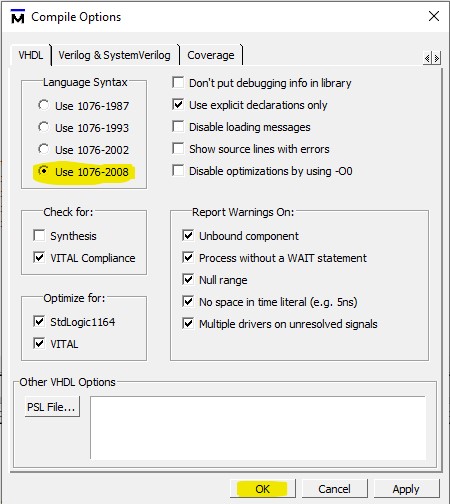
Note how the report strings are constructed by concatenation. If you want to use to_string in this way, then you may need to change the VHDL version in ModelSim.
From the dialog box that appears, choose the VHDL tab and choose 1076-2008 as the version.