Digital computers store and manipulate binary numbers. For some applications, binary numbers are used to represent a waveform voltage.
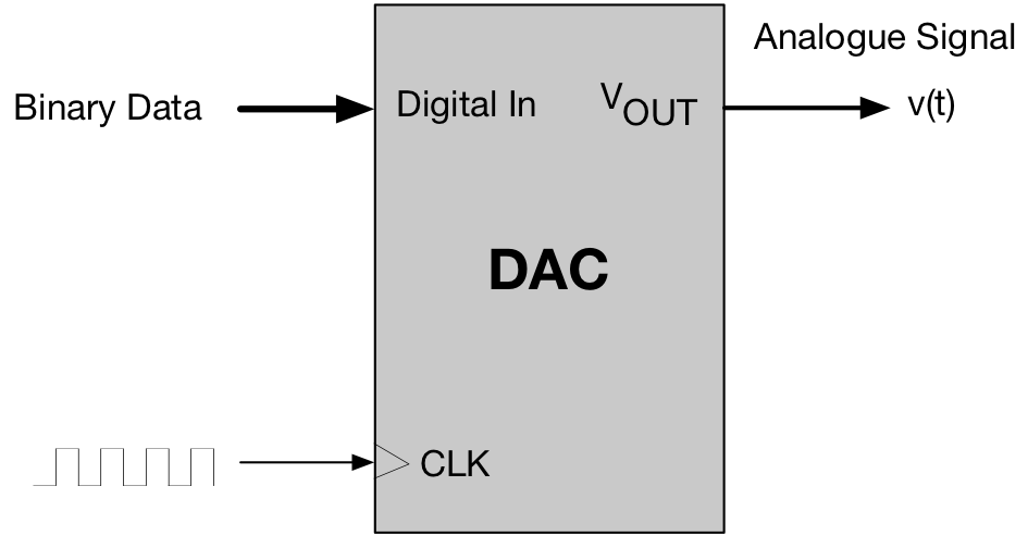
The Digital to Analogue Converser (DAC) is a device that converts a binary representation of a number to an actual analogue voltage on an external pin.
Different DAC devices have different resolutions. On this course, we are using a 12-bit DAC which can represent  distinct voltage levels, ranging between 0V and the supply voltage.
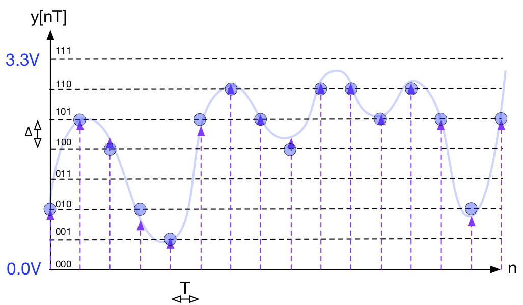
Below is the same diagram used for the glossary entry on the ADC. The difference is that the process is the reverse of that of the ADC. For the DAC, the digital signal is the input and the analogue value (circles) represent the outputs (only three bits have been used here for clarity).
The digital inputs are either parallel (for a 12-bit input, there would be 12 input pins) or serial (where there is only one digital input pin).
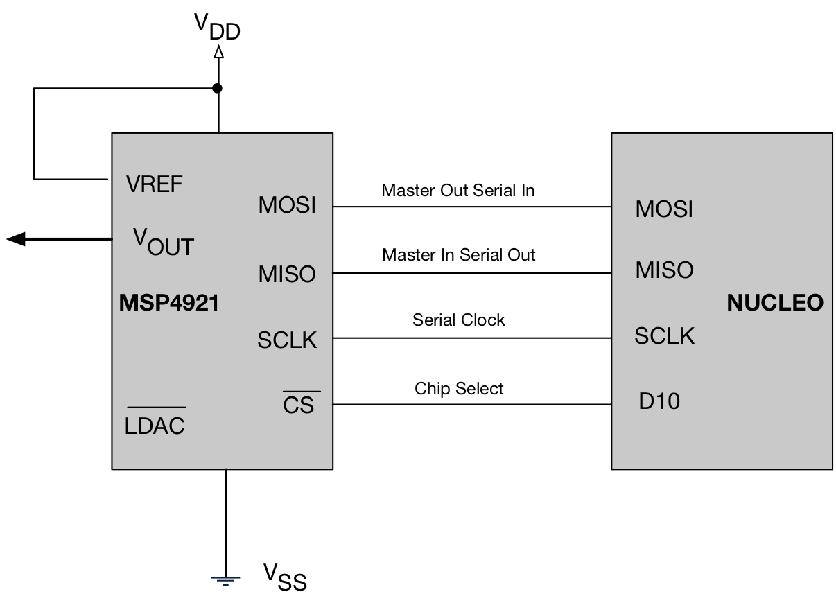
For serial input, each bit of the data word is sent in sequence. For the device we are using on this module, the diagram below depicts how the digital data (originating from the microcontroller) is interfaced to the DAC using a standard interface known as SPI.
Note that a clock is used to synchronize the data transfer. Once all the data bits are received, the DAC activates internal electronics to convert this number into an analogue voltage, that will ultimately be present on the  pin. For this design, when the Chip Select (CS) is pulled HIGH the converted voltage is then held on the output
The resulting waveform from a DAC is quantised. See the entry on the ADC for a discussion on quantisation. Therefore it is common to use a analogue filter to smooth the signal by removing unwanted signal components.