This is a task that requires you the learner to take responsibility for your learning. You will be given a problem statement. In this problem statement are some highlighted key terms / jargon.
- It is your task to research these terms in order to understand the problem and to attempt to solve it.
- Start with the references provided.
- Don’t feel bad if you struggle and feel free to work with others to try and tackle this problem.
Intended Learning Outcomes
- Calculate the total resistance of two resistors in series
- Calculate the total resistance of two resistors in parallel
- Calculate the current through two resistors in series
- Derive the equation for potential division using two resistors
- Use a potential divider to create a voltage reference
- Calculate the Thévenin equivalent circuit of a potential divider voltage source.
- From (6), describe the trade offs between power consumption, noise and output resistance.
Problem Statement
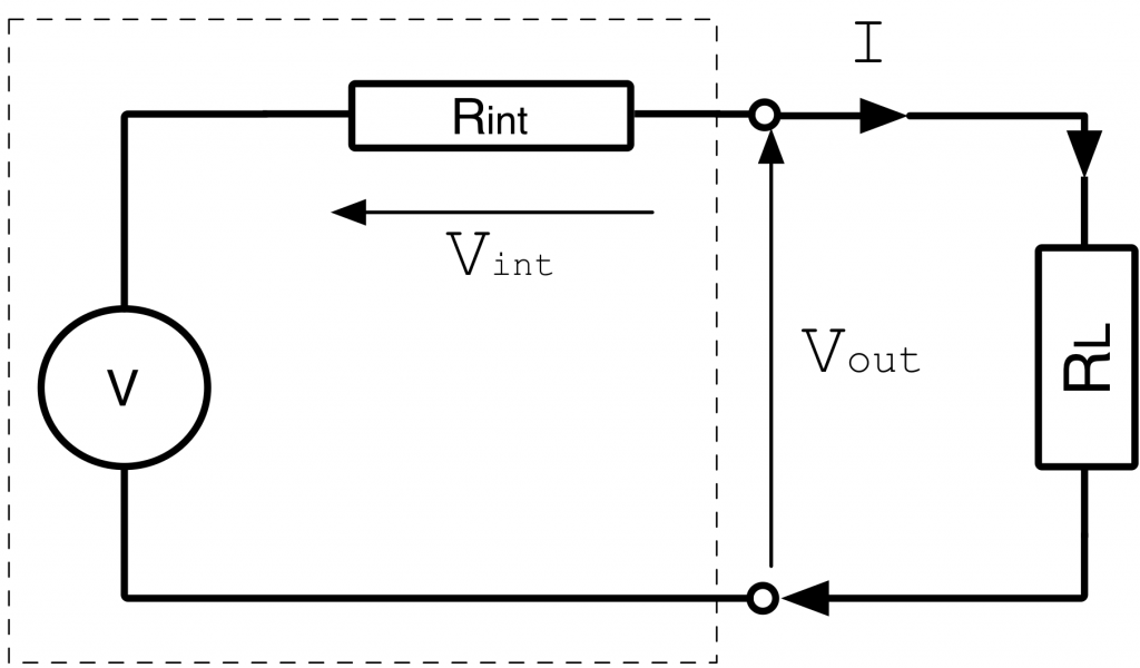
Real world voltage sources can be modeled as an ideal voltage source V and an internal resistor, as shown below. The power supply on the Nucleo Board is 3.3V, with a small internal resistance. For the purposes of this exercise, we will ignore this internal resistance and assume it to be close to ideal.
Problem A (everyone)
Using the Nucleo Board power supply and two resistors,
- design a potential divider circuit to create a
 voltage reference using two resistors. The quiescent current should be
- calculate the series resistance of the two resistors
- calculate the quiescent power consumption of your design (when not under load). Quote your answer in milliwatts (mw).
Problem B (advanced)
NOTE – Only attempt this if you are very confident and/or have plenty of spare time!
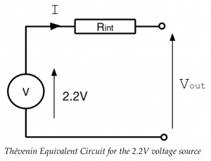
Derive the Thévenin equivalent circuit for the voltage source (see over) of this new 2.2V source.
- What is the internal resistance
 ?
? - If this new voltage source were to drive a
 load, what would be the output voltage Vout?
 - If this new voltage source were to drive a
 load, what would be the output voltage
  ?
? - What changes would you have to make to make this suitable for driving a load? How would this impact on quiescent power consumption?
Comment on the suitability of a voltage divider as a power supply.
References
[1] Ohms Law, BBC BiteSize, http://www.bbc.co.uk/schools/gcsebitesize/science/edexcel_pre_2011/electricityintheory/voltagecurrentresistancerev3.shtml, accessed 27/09/2018
[2] Voltage divider tutorial., https://www.youtube.com/watch?v=XxLKfAZrhbM, accessed 27/09/2018
[3] Voltage Dividers, https://www.youtube.com/watch?v=AyB2kXThlvE, accessed 27/09/2018
[4] Thévenin’s theorem., https://en.wikipedia.org/wiki/Thévenin%27s_theorem,accessed 27/09/2018
Feedback
If you wish to leave feedback or have a question, please use the form below.
[contact-form][contact-field label=”Name” type=”name” required=”true” /][contact-field label=”Email” type=”email” required=”true” /][contact-field label=”Website” type=”url” /][contact-field label=”Message” type=”textarea” /][/contact-form]