In this section, we will look at digital inputs, and how we might use them to control digital outputs. We will be using a simple “push-to-make switch” to generate a single digital bit of data.
Intended Learning Outcomes
- Configure an digital input with a push to make switch
- Use a pull up/down resistor to avoid floating inputs
- Write software to read a switch state
- Use programming methods to avoid switch bounce
- Control multiple digital outputs with binary numbers
- Use binary operators to manipulate binary numbers
Activity 3.1 – Simple Switch Input
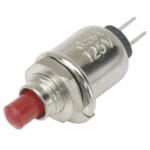
Remember that a single digital signal is either ON or OFF. Numerically, we represent this as 1 or 0 (a single binary digit). The simplest way to generate a single bit input signal is with a push switch.
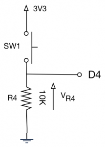
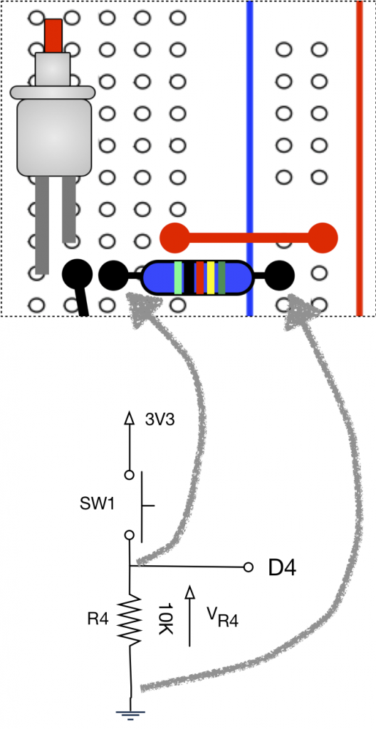
The schematic to generate a digital input is as follows.
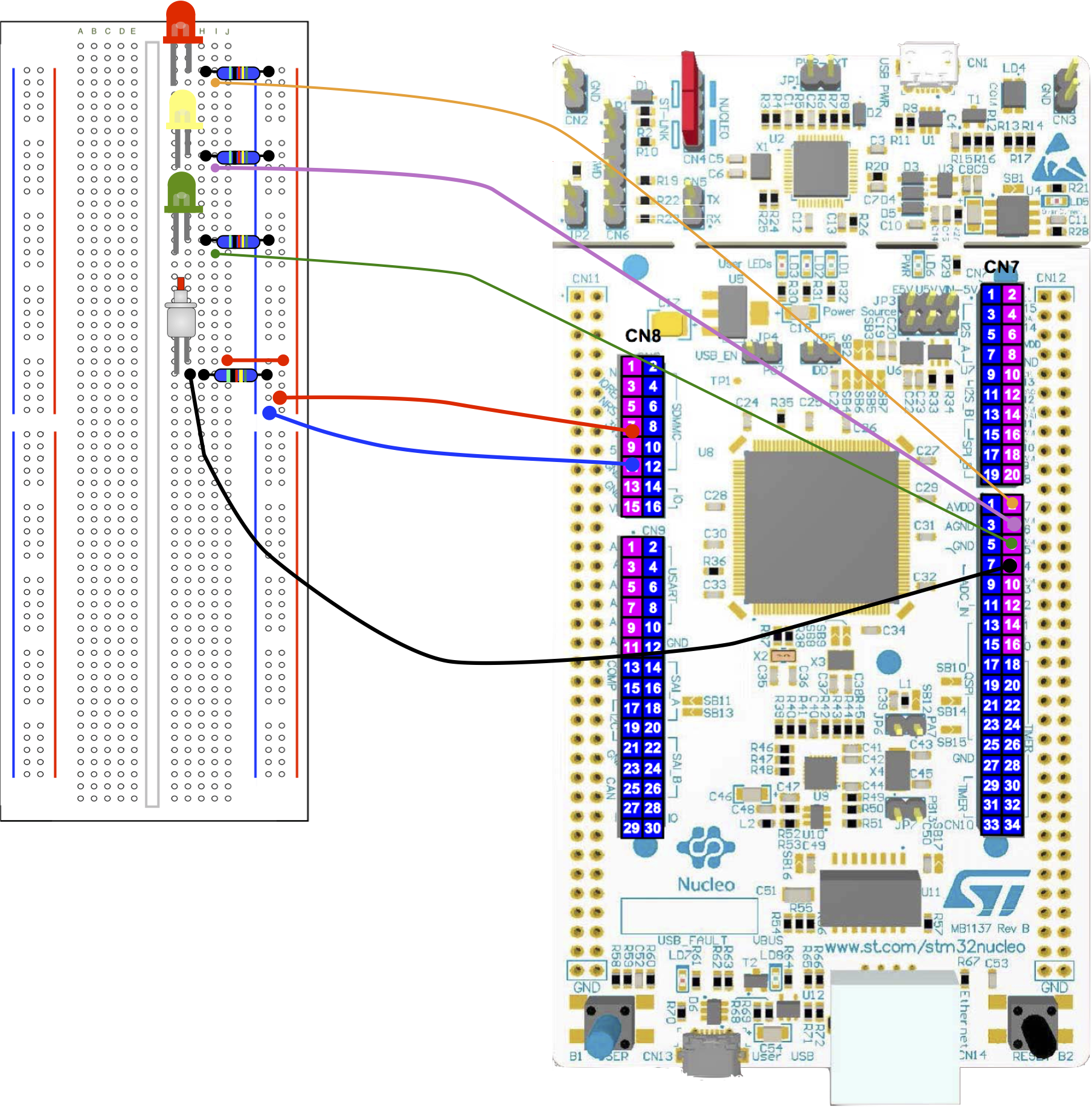
In addition to the switch, wire up 3 LED’s as shown here.
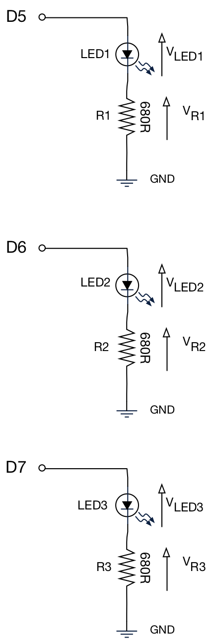
These will be used for outputs.A suggested prototype board layout is shown below:
Task 3.1.1
In the first task, we are simply going to observe the digital input with a DVM when the =button is pressed and released.
| Using the digital volt meter, measure the voltage across R4 when the button is pressed, and when it is released |
| Tip – this can be tricky, so get someone to press and release the button for you while you hold the DVM leads. |
Activity 3.2 – Reading Digital Inputs
For this task, we are going to read the digital input using software. The objective is as follows:
- When the user depresses a button, the red LED switches ON and stays ON (until the system is reset).
Remember – the input is connected to D4. Maybe unsurprisingly, we use a component called a DigitalIn .
Task 3.2.1
| Create a new project and paste in the code below. Build and run to test. |
| When the yellow and green lights come on, press and release SW1. |
| Press the black RESET button on the Nucleo board to run again. |
#include "mbed.h"

DigitalOut  red_led(D7);
DigitalOut  yellow_led(D6);
DigitalOut  green_led(D5);
DigitalIn   SW1(D4);

int main() {

    //Switch on Yellow and Green to indicate
    //that the code is running
    yellow_led = 1;
    green_led = 1;
    red_led = 0; //Set RED LED to OFF

    // Wait for SW1 to be pressed
    while (SW1 == 0) { }

    red_led = 1;	//Turn ON LED

    while (1) { }		//Repeat forever
}
Once again, we use of the the component from Mbed to make interfacing with hardware simple.
DigitalIn SW1(D4);
where SW1 is an instance of DigitalIn , which can read pin D4 . A critical line in this code is as follows:
while (SW1 == 0) { }
While the digital input SW1 is equal to zero, run the (empty) code block between the curly braces and then repeat.
NOTE:
the operator == is used to test for equality.
the operator = is used to assign a value (from right to left)
It is very easy to get these confused!
Once the switch is pressed, an attempt to read SW1 will return a 1. The condition SW==0 will now be false, so the while loop will exit and run to the next statement. The next statement switches on the red LED.
red_led = 1;
Let’s recap the syntax of a while loop.
while (<condition to enter the loop>) {

    // Loop body

}
In words:
”If the condition is met, execute the code in the loop body and then repeat, otherwise exit and continue executing the next statement.”
A graphical depiction of this this is given in the glossary.
Task 3.2.2
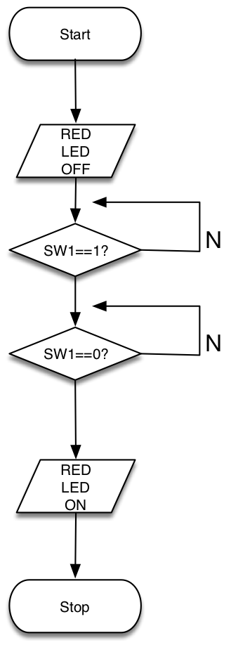
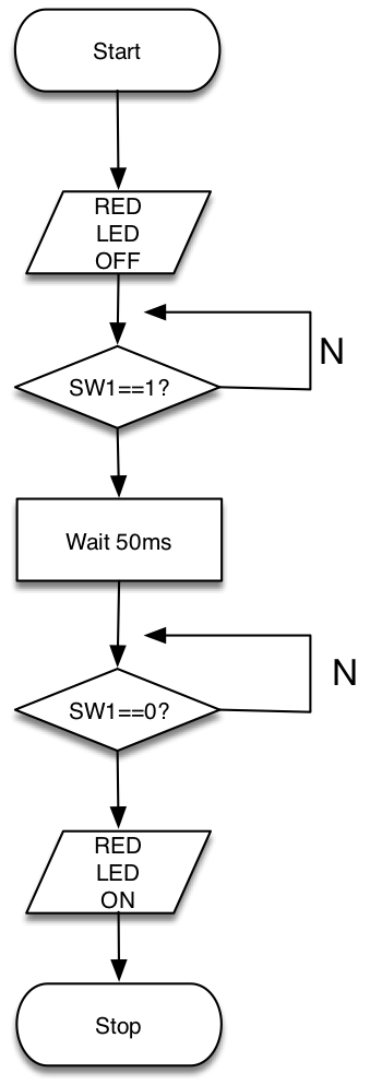
| Modify the code so that the red LED only comes on after the SW is pressed and then released |
| Hint: follow the flow chart below |
| Test your solution. Is it entirely reliable? Can you improve on it? |
You probably found this to be an unreliable solution. In the next section, you will learn about “switch bounce” and how to avoid it.
Switch Bounce
The reality is that mechanical switches are not perfect. Most switches suffer switch bounce to some extent. An ideal switch signal might be assumed to be a step waveform, as depicted below.
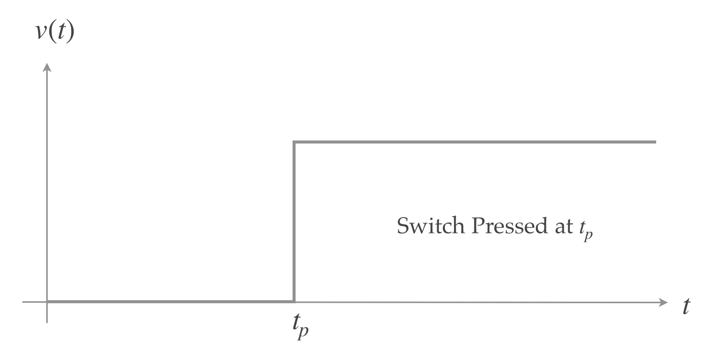
In reality, this is never the case. It is impossible for a signal to change instantaneously. Furthermore, at the moment switch contacts make or break, partial connections and disconnections may occur, resulting in a phenomena known as switch bounce. This is depicted in the figure below:
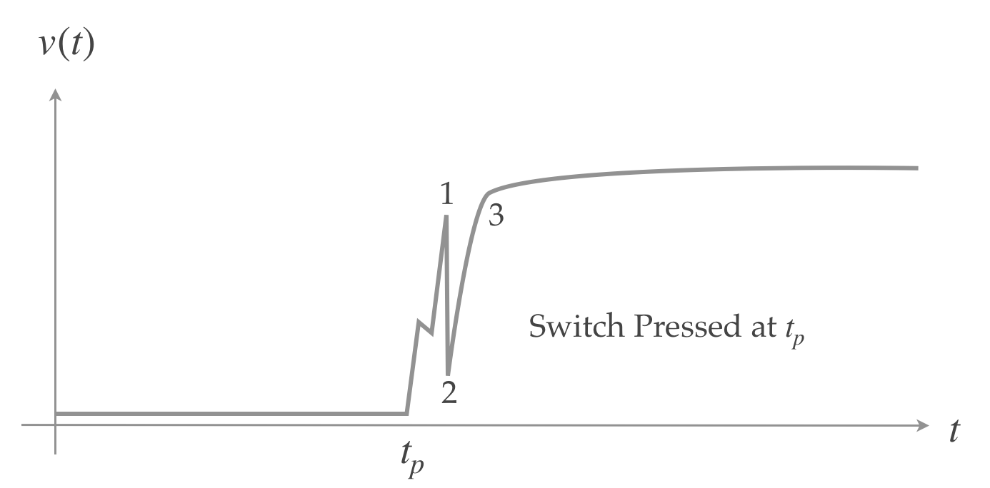
As you can see in the second diagram, the waveform is not a perfect step like the ideal.
There are a number of additional phenomena we much consider:
- Noise – random signals superimposed on top of the waveform. This can originate from internal sources, including the electronic components in your circuit and external sources, such as strip lighting, radio transmitters and other nearby electronic devices.
- Reactive effects – if you’ve not studied reactance yet, it should suffice to say that perfect step waveforms are almost impossible – signals often rise as an exponential curve (although it might be very rapid) and can even “ring” (overshoot) due to stray intrinsic reactive effects of components, connectors and electronic components.
This reinforces the points that electronics is ultimately analog and signals are rarely ideal.
A problem with such phenomena is that their occurrence is stochastic (random, probability based). An engineer must be mindful of such issues, and design systems to minimize the probability of such events occurring or causing malfunction, especially in safety critical systems.
In the case of switch bounce, the exact nature is highly unpredictable.
Task 3.2.3
Consider the following revised flow-chart below. This has added a delay after the first press is detected.
| Modify the code to add this delay |
| Does it impact on the user experience? Is the delay long enough? |
| What would happen if you made the delay too long (e.g. 5s)? |
| hint: use the wait function that we used yesterday |
Adding the delay adds what is often known as latency.
This task illustrates a few key points:
- electronic signals are rarely “ideal”
- switch inputs suffer “switch bounce”
- we sometimes have to make trade-offs, such as reliability and latency
Activity 3.3 – Multiple Outputs
The mbed.com website contains a lot of useful reference and tutorial information. A great place to start is the online documentation https://os.mbed.com/docs/latest
Much of what we have used to far can be found under the section on Driver APIs https://os.mbed.com/docs/latest/apis/drivers.html
So far, we have only read from a single input pin or asserted a single output pin at a time. We often want to read groups of pins at the same time*
*remember that integer values can be represented in binary as groups of bits (also known as a bus).
Consider all 3-bit binary numbers in the table below.
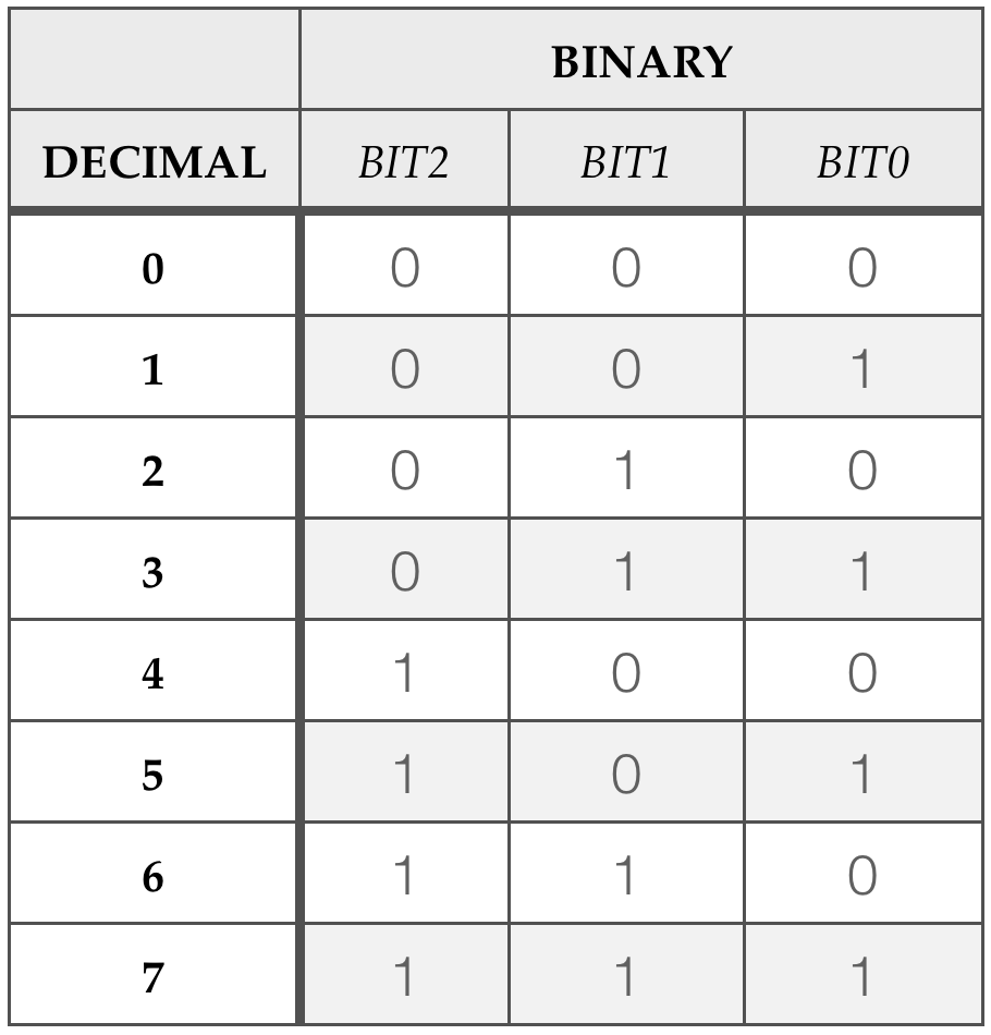
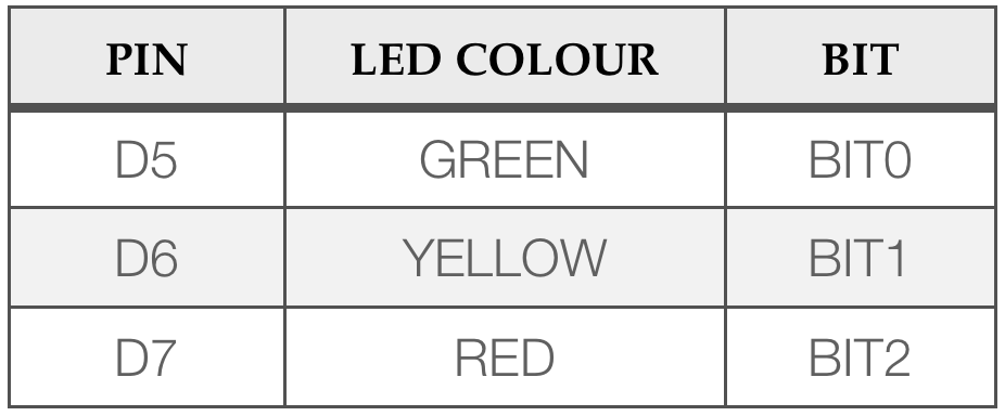
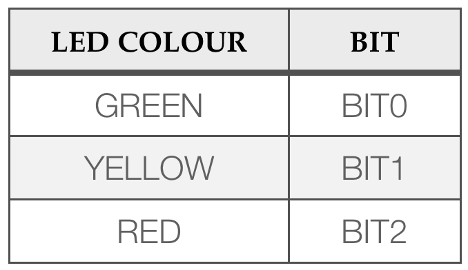
In the next task, we are going to convert decimal numbers to binary using the LEDs as an output display. The red LED will be the most significant bit (BIT2) and the greed LED the least significant bit (BIT0).
Task 3.3.1
Follow the steps in the following table
| Create a new project |
| Paste in the code below |
| Try setting binaryOutput to different values (0..7) |
| Do you see the binary equivalent displayed in the LEDs? If not, ask the tutor to explain (this is rather critical!) |
| What happens if you set binaryOutput to a value greater than 7? (hint : work out what the binary equivalent, then compare) |
#include "mbed.h"

//lsb first
BusOut binaryOutput(D5, D6, D7);

int main() {

    //Try different values
    binaryOutput = 3;

    while (1) { }
}
The new component is BusOut which takes a variable number of parameters. These parameters specify (lsb first) which pins to use for the binary output.
Assigning a decimal to the instance “binaryOutput” converts the decimal to binary, and sets the pins accordingly.
Exhaustively testing all values between 0 and 7 is fairly time consuming, especially if you needed to repeat the tests.
Next we are going to use variables and while loops to cycle through the numbers 0..7 automatically.
Task 3.3.2
In the code below we use a do-while loop. See the glossary / lecture slides for a reminder on how do-while loops work.
#include "mbed.h"

BusOut binaryOutput(D5, D6, D7);
//DigitalIn SW1(D4);

int main() {

    unsigned int uiCount = 0;

    while(1) {

        do {
            //Write decimal to the output
            binaryOutput = uiCount;

	    //Increment the count using +
            uiCount = uiCount + 1;
            wait(1.0);              //Delay for 1s

	         //Condition to repeat
        } while (uiCount < 8);

        //Reset the count
        uiCount = 0;

    } //end while(1)
} //end main
| Create a new project |
| Paste in the code code above |
| Run the code and observe the outputs |
| Modify the code to count down from 7..0 |
| hints: you will need to change the condition to re-enter the loop; note that uiCount is unsigned, so cannot be negative. If you get stuck, you can ‘peek’ at the solution. |
Activity 3.4 Bitwise Operators
A very important skill is to be able to manipulate individual bits in an integer variable. This includes:
- Setting – refers to setting a specified bit (or group of bits) to 1 without affecting the others.
- Resetting – Same as setting, only setting to 0 instead of 1
- Toggling – refers to flipping a specified bit (or group of bits) to their opposite state (0 to 1 or 1 to 0), again without affecting the others.
- Logical Shift left – all bits move one position to the left, a zero is pushed in from the right and the most significant bit(s) is lost
- Logical Shift right – all bits move to the right, the least significant bit(s) is lost and a zero is pushed in from the left
These operations can be performed using “logical operators”. These are summarised below (see lecture slides for examples).
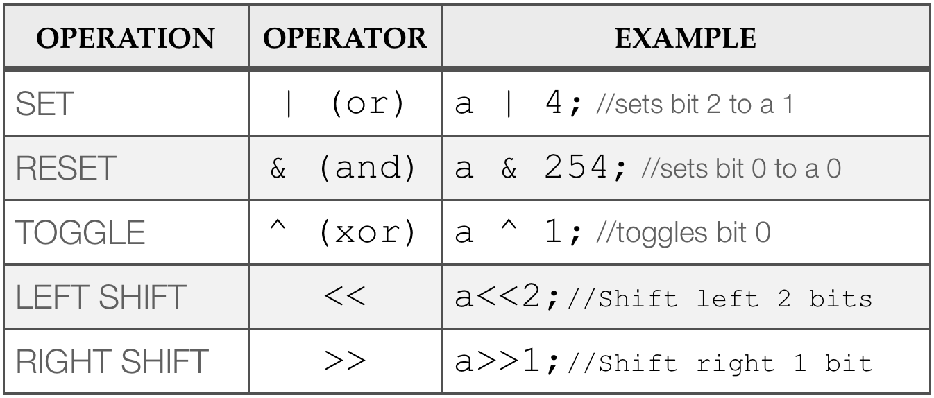
Setting A BIT
Consider the example where the unsigned integer variable  is equal to binary
  . In decimal this is equivalent to
  . If we SET bit 0 to a 1, we get binary
  , which is equal to decimal 5.
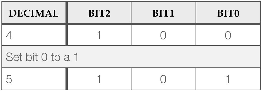
Note how only bit 0 is changed, and the others are left unaffected. How is this done in code? We use the logical OR operator | , which looks like a vertical bar (see the glossary for a reminder).
Task 3.4.1
Complete the following:
| Create a new project |
| Paste in the code code below |
| Read the comments and complete the code |
#include "mbed.h"

//Global objects
BusOut binaryOutput(D5, D6, D7);
DigitalIn SW1(D4);

//Function prototypes
void waitForButtonPress();

//Main function
int main() {

    //Create a variable to hold the bit pattern
    unsigned int u;

    //Flash LED's to indicate the code is running
    binaryOutput = 7;
    wait(0.5);
    binaryOutput = 0;

    //Main Loop
    while(1) {

        u = 0;             //Set initial value
        binaryOutput = u;  //Show binary on LED's
        waitForButtonPress();   //Call function

        //Here is the first - use | to set bit 1
        u = u | 2;        //OR with binary 010
        binaryOutput = u;
        waitForButtonPress();

        //Modify u with the | to set bit 2
        //WRITE CODE HERE

        binaryOutput = u;
        waitForButtonPress();


        //Modify u with the | to set bit 0
        //WRITE CODE HERE

        binaryOutput = u;
        waitForButtonPress();

    } //end while(1)
} //end main


//This is known as a C function.
//This saves a lot of code repetition
void waitForButtonPress() {
    while (SW1 == 0);
    wait(0.25);
    while (SW1 == 1);
}
 Remember the green LED is the least significant bit (bit 0). You can look at the solution if you are stuck.
Resetting a bit
Consider the example where the unsigned integer variable is equal to binary 110. In decimal this is equivalent to 
If we RESET bit 1 to a 0, we get binary 100, which is equal to decimal 4.
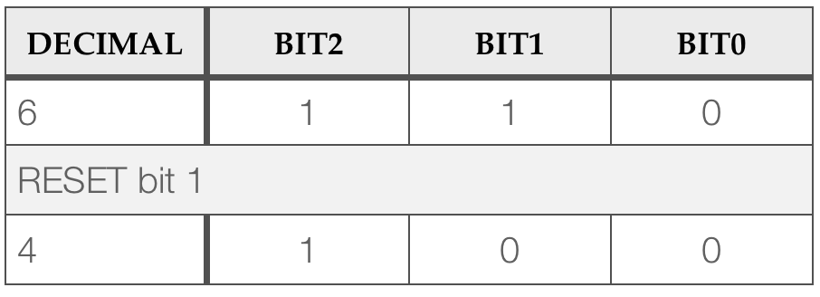
Note again how only a single bit (bit 1) is changed, and the others are left unaffected. This time we use the logical AND operator & (see the glossary/lecture slides for a reminder).
Task 3.4.2
Perform the following:
| Create a new project |
| Paste in the code (see below) |
| Read the comments and complete the code. If you are stuck or wish to check your answer, a solution is here |
#include "mbed.h"

//Global objects
BusOut binaryOutput(D5, D6, D7);
DigitalIn SW1(D4);

//Function prototypes
void waitForButtonPress();

//Main function
int main() {

    //Create a variable to hold the bit pattern
    unsigned int u;

    //Flash LED's to indicate the code is running
    binaryOutput = 7;
    wait(0.5);
    binaryOutput = 0;

    while(1) {

        u = 7;             //Set initial value 111
        binaryOutput = u;  //Show binary on LED's
        waitForButtonPress(); //Call function

        //Use & to reset bit 1
        u = u & 5;          //AND with binary 101
        binaryOutput = u;
        waitForButtonPress();

        //Modify u with & to reset bit 2 to a 0
        //WRITE CODE HERE
        binaryOutput = u;
        waitForButtonPress();


        //Modify u with & to reset bit 0 to a 0
        //WRITE CODE HERE
        binaryOutput = u;
        waitForButtonPress();

    } //end while(1)
} //end main


void waitForButtonPress() {
    while (SW1 == 0);
    wait(0.25);
    while (SW1 == 1);
}
Bit Toggling
When a bit is flipped to the opposite state, we call this toggling.
Consider the example where the unsigned integer variable is equal to binary 100. In decimal this is equivalent to . If we TOGGLE bit 1, we get binary 110, which is equal to decimal 6. If we repeat the process, we get back to binary 100 again.
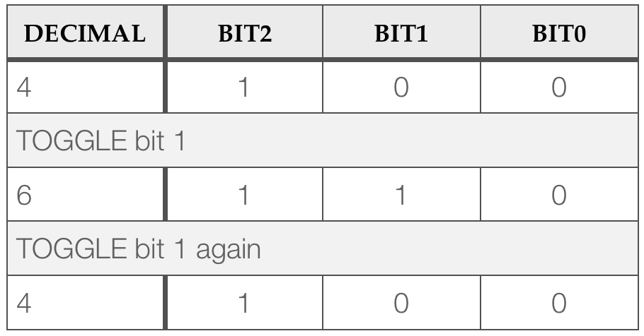
Again we are only affecting a specific bit (bit 1), with the others are left unaffected. This time we use the logical XOR operator ^ (see the glossary for a reminder).
Task 3.4.3
Perform the following:
| Create a new project |
| Paste in the code (see below) |
| Read the comments and complete the code. A solution is available here. |
#include "mbed.h"

//Global objects
BusOut binaryOutput(D5, D6, D7);
DigitalIn SW1(D4);

//Function prototypes
void waitForButtonPress();

//Main function
int main() {

    //Create a variable to hold the bit pattern
    unsigned int u;

    //Flash LED's to indicate the code is running
    binaryOutput = 7;
    wait(0.5);
    binaryOutput = 0;

    while(1) {

        u = 0;             //Set initial value 0
        binaryOutput = u;  //Show binary on LED's
        waitForButtonPress(); //Call function

        //Use & to toggle bit 0
        u = u ^ 1;          //XOR with binary 001
        binaryOutput = u;
        waitForButtonPress();

        //Toggle bit 1
        //WRITE CODE HERE
        binaryOutput = u;
        waitForButtonPress();


        //Toggle bit 2
        //WRITE CODE HERE
        binaryOutput = u;
        waitForButtonPress();

        //Toggle bits 0 and 2
        //WRITE CODE HERE
        binaryOutput = u;
        waitForButtonPress();

        //Toggle all bits
        //WRITE CODE HERE
        binaryOutput = u;
        waitForButtonPress();

        //Toggle all bits
        //WRITE CODE HERE
        binaryOutput = u;
        waitForButtonPress();

    } //end while(1)
} //end main


void waitForButtonPress() {
    while (SW1 == 0);
    wait(0.25);
    while (SW1 == 1);
}
Logical Inverse (NOT)
In the last example, you may have observed that all bits could be toggled when you XOR a 1 with ALL bits. A simpler and (computationally) faster option is to use a Logical Inverse.
Consider the example where the unsigned integer variable is equal to binary 010. In decimal this is equivalent to  .
.
If we INVERT , we get binary 101, which is equal to decimal 5. If we repeat the process, we get back to binary 010 again.
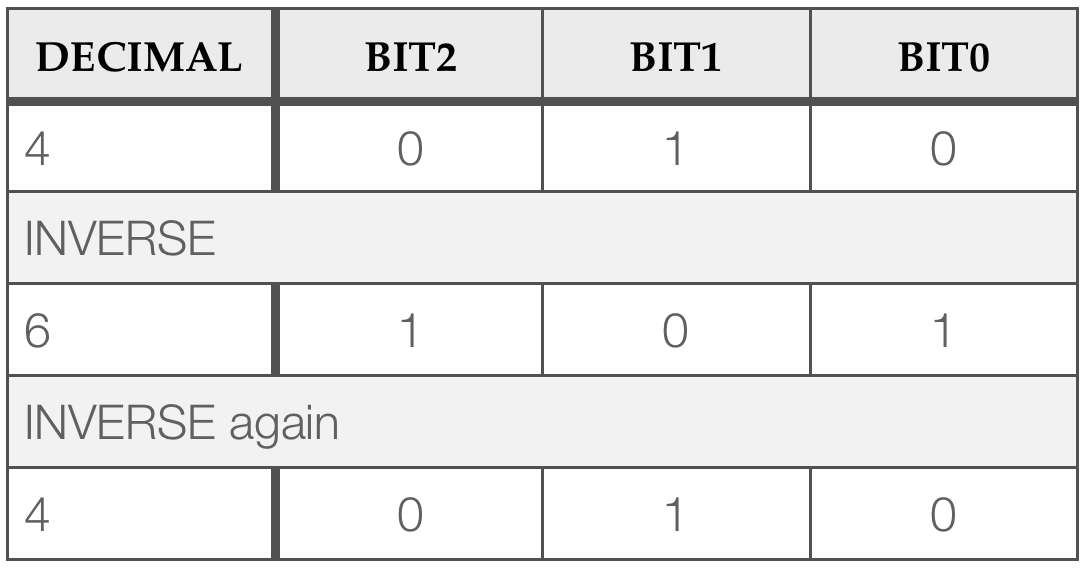
Unlike previous examples, the inverse affects ALL bits. This time we use the logical NOT operator ~ (see the glossary for a reminder).
Logical shift
Other useful and commonly used operators are the logical shift right and left operators.
Consider the example where the unsigned integer variable is equal to binary 001. In decimal this is equivalent to  .
.
If we LEFT SHIFT , we get 010. LEFT shift again, and we get 100. Now right shift, and we get 010 again etc.
- For a 1-bit LEFT SHIFT, the bits are moved one position to the left and a zero is pushed into the least significant bit position.
- For a 1-bit RIGHT SHIFT, the bits move once position to the right and a zero is pushed into the most significant bit position.
It is also possible to shift multiple positions at a time. The operations described here are known as a logical shift. There is another type, known as an arithmetic shift, but until we cover 2’s compliment arithmetic (signed numbers), discussion of this will be deferred.
Task 3.4.4
Perform the following:
| Create a new project |
| Paste in the code (see below) |
| Read the comments and complete the code |
Hint: You could use the right shift, but actually you can do this much more simply. Think about the pattern / states:
G Y R Y (now repeat)
Some of this is already covered. You just need to add one more state.
#include "mbed.h"

//Global objects
BusOut binaryOutput(D5, D6, D7);

//Main function
int main() {

    //Create a variable to hold the bit pattern
    unsigned int u;

    while(1) {

        u = 1;             //Set initial value 0
        int count = 0;
        while (count++ < 3) {
            binaryOutput = u; //Write to LEDs
            u = u << 1;       //Shift left 1 bit
            wait(0.25);       //Wait
        }

// TODO: Make the pattern shift in the opposite // direction
// (also known as the Knight Rider pattern)


    } //end while(1)
} //end main
Activity 3.5 – Review
In this section, there are some additional advanced tasks and a set of review questions. In some cases, you might want to write some code to check your answers. In other cases, you might need to refer back to the lecture slides.
Additional Task 3.5.1
There are bugs in the code below. Can you find and correct it?
#include "mbed.h"

BusOut binaryOutput(D5, D6, D7);

/*
 **************************************************************************
 CAN YOU FIND THE BUGS IN THIS CODE?
 One problem only shows itself when you run the sequence the first time ;o)
 **************************************************************************
 */

int main() {

    int iCount = 7;

    //Repeat this program forever
    while(1) {

        do {
            binaryOutput = --iCount;  //Write decimal to the output and decrement
            wait(1.00);             //Delay for 500ms
        } while (iCount > 0);       //Condition to repeat

        //Reset the count
        iCount = 7;
    }
}
Additional Task 3.5.2
(Do this task if you have spare time)
This task is a continuation from 3.5.1.
| Wire up an additional switch and connect to D3 |
| Create a project and paste in the code below |
| Build and run the code, and try pressing different switch combinations |
| Q1. With both switches pressed, what is delay between the LEDs changing state? |
| Q2. Which logical operator is performed using the ^ operator? |
| Q3. Which input (D3 or D4) is the least significant bit in the input binaryInput? |
| Q4. Could you use two DigitalIn objects instead of a BusIn? If so, how? ( a solution is given here ). Answers to Q1-3 are here. |
#include "mbed.h"

//Global objects
BusOut binaryOutput(D5, D6, D7); //Outputs as an integer
BusIn binaryInput(D3, D4); //Inputs as an integer


//Main function
int main() {

    //Create a variable to hold the bit pattern
    unsigned int u = 7;

    while(1) {

        binaryOutput = u;    //Write to LEDs

        //TOGGLE all 3 bits in u
        u = u ^ 7;

        //Calculate the delay
        double delay = (double)(binaryInput+1);
        wait(delay * 0.25);          //Wait

    } //end while(1)
} //end main
Feedback
If you wish to leave feedback or have a question, please use the form below.
[contact-form][contact-field label=”Name” type=”name” required=”true” /][contact-field label=”Email” type=”email” required=”true” /][contact-field label=”Website” type=”url” /][contact-field label=”Message” type=”textarea” /][/contact-form]