Digital signals typically take one of two values. We often consider the “Voltage” at a point in a circuit to take one of the following two states:
ON/OFF

1/0

HIGH/LOW

TRUE/FALSE

3.3V/0.0V

5.0V/0.0V
In all the above cases, the electrical voltage is considered to be in only one of two states, and which notation we use often depends on the practical application or type of theoretical analysis we are performing.
In practice, if we examine real-world signals closely, we see minor variations (typically noise or artifacts). Digital systems are in fact Analogue systems that use high gain amplifiers to switch signals rapidly been two values (or ranges of values).
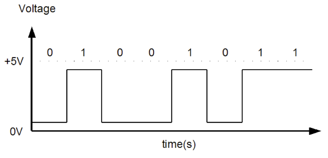
A single digital signal is known as a ‘bit’.
- Mathematically we see this as taking the value of 0 or 1.
- In physical terms this might be 0V and 3.3V
When you group many digital signals/bits together, you can build representations of larger numbers and create a binary integer. Each combination represents a unique decimal value.
- A group of 8 bits, typically known as a byte, can represent 256 different combinations. Computer data are often organized into bytes.
- A group of 16 bits can represent 65536 different combinations (0..65535). For example, this is used to represent an “sample” of an analogue voltage in a compact disc.