This is section,we look at ways to output analogue signals. For this we use two techniques: Pulse Width Modulation (PWM) and a Digital to Analogue Converter (DAC). The microcontroller we are using does in fact have an on-chip DAC, but as no all devices do, we have included an example of interfacing to an external device. We achieve this using an industry de facto standard known as the Serial Peripheral Interface (SPI).
Intended Learning Outcomes
- Define the meaning of PWM and calculate the RMS voltage of a PWM signal
- Use PWM to create a known average voltage
- Program a PWM peripheral
- Program the internal DAC with the DigitalOut class
- Use the SPI interface to interface to an external DAC
Activity 5.1 Pulse Width Modulation (PWM)
Pulse Width Modulation (or PWM) is a simple technique used to generate an alternating voltage signal with an known “average DC voltage”. The technique is commonly used in control systems, including the control of DC motors.
TASK 5.1.1
| Read the glossary entry on PWM |
| Attempt the short quiz below. |
Q1.For a PWM system, using a pulse of 1V,  and
and  , which of the following is true?
(hover your mouse over the correct answer).
A. The duty is 0.1%
B. The duty is 10%
C. The mean voltage is 0.1μV
D. The mean voltage is 10V
Q2. For a PWM system, using a pulse of 10V,  and
and  , what is the mean voltage?
Q3. For a PWM system driving a DC motor, using a pulse of 5V,  and
and  , which of the following is true?
A. The choice of T means motor would be louder than applying a constant voltage
B. This makes no sense as Tmark > T
C. The output voltage would be 3.3V
D. The duty is 20%
Activity 5.2 Pulse Width Modulation (PWM) with Timers
In this task we will implement PWM using a a simple timer.
| Build and run the code shown below (also on mbed) |
| What are the ON and OFF times? |
| Try different values of R |
#include "mbed.h"

//Time period
#define T 0.001

//Mark-Space Ratio
#define R 0.1

//Mark and Space times
#define Tmark (R*T)
#define Tspace ((1.0-R)*T)

DigitalOut onboardLed(LED1);
DigitalOut redLED(D7);

int main() {
   printf("\nWelcome to ELEC143\n");

   while (1) {
      redLED = 0; //Space
      wait(Tspace);
      redLED = 1;	//Mark
      wait(Tmark);
   }
}
Task 5.2.2
Perform the following:
| Now try and modify task 5.2.1 to also independently set the brightness of the green LED. If you spend more that 10 minutes on this task, maybe stop. The point of this exercise is to illustrate the difficulty (there is an easier way)! |
| If you have succeeded, consider how you might now also control the brightness of the yellow LED? |
| Describe what problems you encounter |
There are many ways to try and solve this problem. I have gone for a solution that uses timer interrupts (although even this is not perfect).
What you might find is that your solution does not “scale” beyond one or two LEDs. One of the fundamental problems here is that the wait statement is “blocking” (you cannot do anything else unless you use an interrupt).
There are a number of elegant solutions. Timers are one possibility (as I have used), but you might want to reserve those timers for other tasks. I’ve kept the interrupt routines as short as possible to avoid latency issues (in the event two overlap in time such that one has to wait for the other to finish).
Luckily, PWM is a common requirement and this problem was recognized a long time ago, and this microcontroller comes with PWM controllers built in! These controllers have their own timers and logic to control the output, so all run independently in parallel.
Remember: a single core microcontroller can only really execute one instruction at a time. Any attempt at multitasking is always an illusion and often comes with compromises.
Look at the code below to see how simple it is to use a PWM in Mbed-os on this device. Note for the F429 board, I’ve moved the RED LED to pin D6. You should modify your hardware accordingly.
#include "mbed.h"

DigitalOut OnBoardLed(LED1);

#ifdef TARGET_NUCLEO_F429ZI
PwmOut pwmRed(D6);  //D7 is not a PWM output on the F429, so use D6 instead
#else
PwmOut pwmRed(D7);
#endif

int T = 10;
int Tmark = 5;

int main() {

    pwmRed.period_us(T);
    pwmRed.pulsewidth_us(Tmark);

    while(1) {
        //Heartbeat
        wait(1);
        OnBoardLed = !OnBoardLed;
    }
}
The following should be noted:
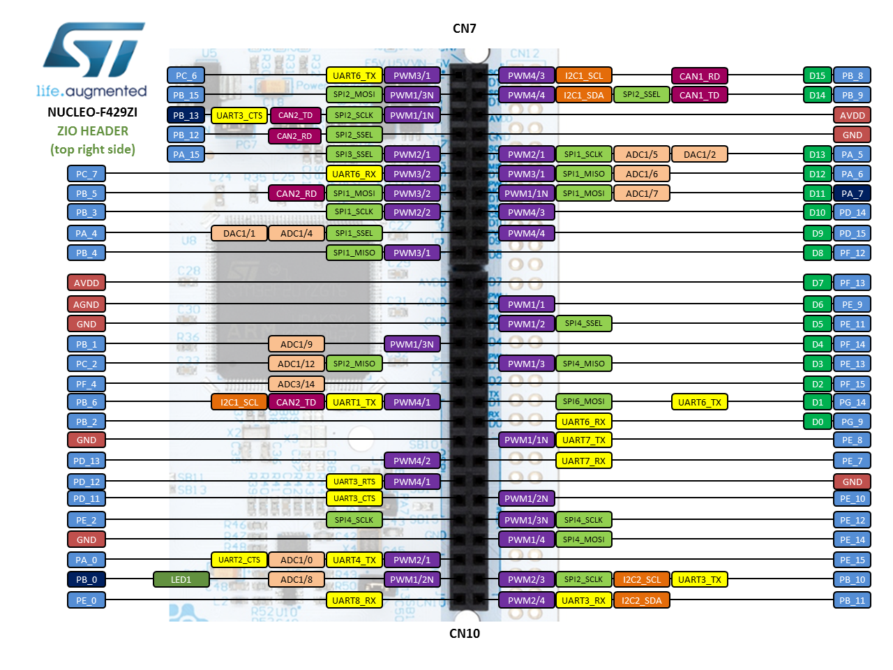
- Not all pins support PWM. See the Mbed hardware page for this board or the figure below (colour coded purple)
- The
sleep()function may be woken periodically by interrupts. This will be covered in level 6 when we discuss real-time operating systems.
Task 5.2.3
Complete the following:
| Using a Ticker object, make the red LED slowly brighten and dim (check the pin can be used for PWM) |
| (you need to smoothly ramp the value of Tmark up and down between 0 and T) |
Additional Task 5.2.4
If you have time, try the following:
| Modify the solution in 5.2.3 to use the mathematical sine (sin) function instead of a linear ramp. |
Advanced Task 5.2.5
If you feel confident, maybe try the following:
| Write some code uses two switches to switch the red LED on and OFF. |
| Press SW1 and the LED fades ON to full brightness |
| Press SW2 and the LED fades OFF |
| Use a PWM object to achieve this |
Digital to Analogue Conversion
PWM is a popular solution for a number of reasons. One reason is that it is relatively simply to connect the microcontroller PWM output directly to power transistors. Such devices are capable of switching the large currents involved in applications such as DC motor control.
You might want to read the glossary entry on the H-Bridge
Important: you must NEVER connect a the microcontroller pin directly to a DC motor. It cannot supply sufficient current and you may even damage the microcontroller!
The downside of PWM is that in the absence of additional electronics, the output is pulsed. What if you wanted to generate a smooth audio output signal, such as a sinewave? With careful design and additional electronics, you can use a PWM for some applications, but a superior solution is to use a Digital to Analogue Converter (DAC).
Some micro controllers have an on-chip DAC. Alternatively you might use an external device, especially if you want something more specialist (e.g. for professional audio). As we have an internal DAC on the STM32F429ZI, we will use this first. Then we will look at using an external device.
Task 5.2.6 Digital Output with DigitalOut
The micro controller you are using in these labs has an on-chip 12-bit DAC. The Mbed-os library provides an object AnalogOut which encapsulates all the necessary code to access the DAC.
Complete the following:
| Modify the code below to generate a 5Hz sinusoidal tone (use the sin function). |
| Observe the output on the scope to check the frequency |
| If you zoom in close, see the quantisation of the signal? |
#include "mbed.h"
#include “math.h"

AnalogOut  aOut(PA_5);

int main(void) {
    while (true) {
       for (float i=0.0f; i<1.0f; i+=0.01f) {
           aOut = i;
           wait(0.001f);  //approx. 1kHz
        }
    }
}
This code is very simple thanks to the AnalogOut class.
It should be pointed out that this code is written for simplicity as opposed to precision – the rate at which the samples are converted is not particularly consistent so this does not reflect best practise
Activity 5.3 Using an external DAC
For this section, we are going to use an 8-pin MCP4921 12-bit DAC from Microchip as depicted in the figure below:
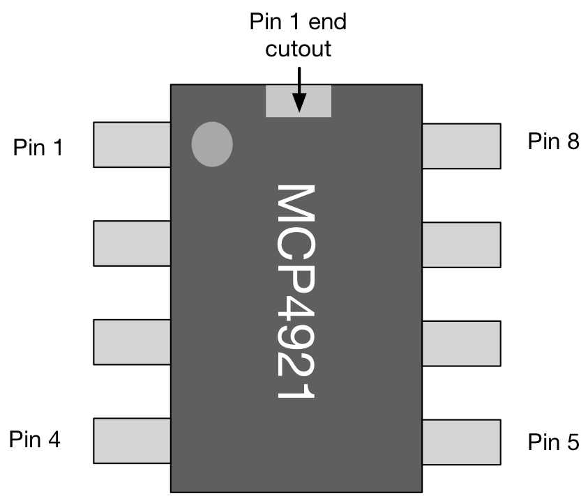
The circle on the package indicates PIN 1. The device we are using is a Dual Inline Package (DIP) which is compatible with prototyping boards. More compact versions are also available if you review the data sheet.
The relevant part of the schematic is shown below
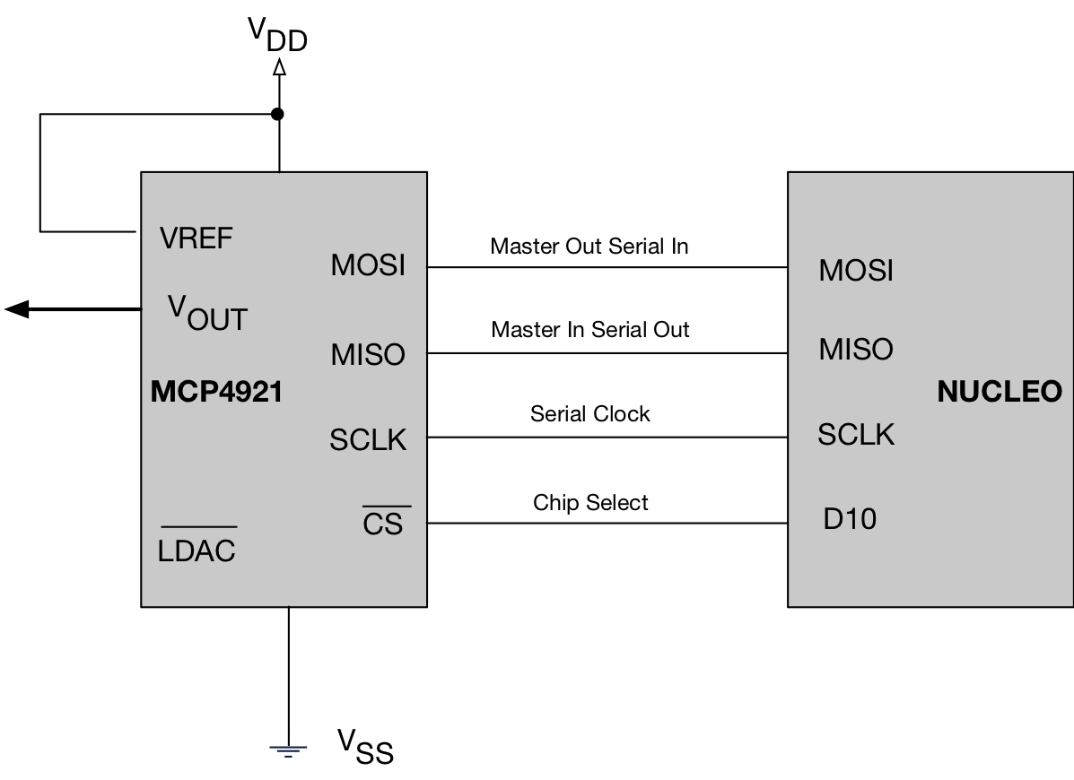
In this schematic, we see the SPI interface.
- The Microcontroller is the master device
- The MCP4921 DAC is the slave
Data is sent one bit at a time from MOSI of the MCU to the MOSI pin of the DAC. To synchronise this, a serial clock is used SCLK. Many SPI devices can be connected, but only one slave device can be selected. We pull the Chip Select (CS) LOW to enable it. This is connected to a GPIO pin D10.
Task 5.3.1
Perform the following tasks:
| TEMPORARILY remove JP6 from your Nucleo Board (to avoid a collision between the Ethernet and the SPI pin D11). Remember to replace it after this experiment! |
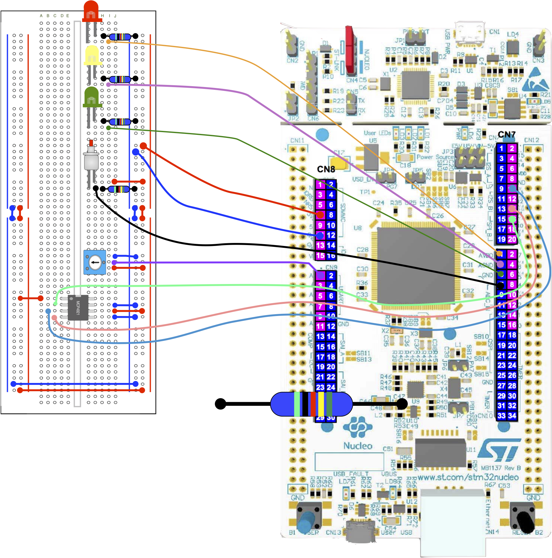
| Wire up the MCP4921 as shown above |
| Build and run the code below |
| Using a multimeter, measure the voltage output (PIN8) of the MCP4921 |
| For an unsigned 12-bit data value, what is the maximum possible value in decimal and HEX? |
Try changing the variable val to the maximum and minimum 12-bit values. Do the output voltages correspond? |
#include "mbed.h"

//This GPIO is used for Chip Select
DigitalOut DAC_CS(D10);

//Status LED
DigitalOut led(LED1,1);

//SPI Object (temporarily remove JP6 when running this)
SPI spi(D11, D12, D13);

//Ticker for setting the output sampling rate
Ticker t;

//Prototype for the ticker ISR
void writeSample();

int main() {

    //Set speed of the SPI interface
    spi.frequency(20000);

    //16 bit words, mode 0 clock
    spi.format(16,0);

    //Write at 1000Hz
    t.attach(writeSample, 0.001);

    while(1) {
        sleep();
    }
}

//ISR for ticker
void writeSample()
{
    //Enable the selected slave device
    DAC_CS = 0;

    //Write a header (top 4 bits) and value (bottom 12 bits)
    unsigned int val = 2048;
    spi.write(0x7000 | val);

    //Disable the selected slave device (and update the output)
    DAC_CS = 1;

    //Status
    led = !led;
}
Task 5.3.2
Perform the following if you have time:
| Modify the code in 5.3.1 to generate a 100Hz sinusoid waveform, and show it on the scope |
| The frequency of the wave is f=10Hz
The output rate Fs = 1000, and T=1/Fs If n is discrete time (increments every T seconds) PI=3.1415926
Note |
| View the result on the scope (you should see something similar to the diagram below) |
 where
where  .
. will range from -1.0 to +1.0, so you need to offset and scale to a 12-bit range.
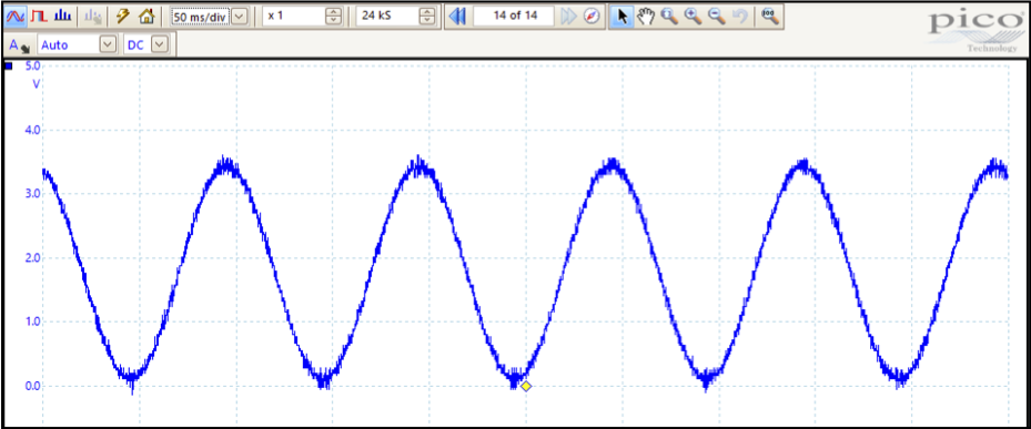
Task 5.3.3
Perform the following tasks:
| Build and run the solution to 5.3.2 |
| Now change the frequency f to 100Hz |
| What do you notice? If this was an audio tone, do you think it would sound good? |
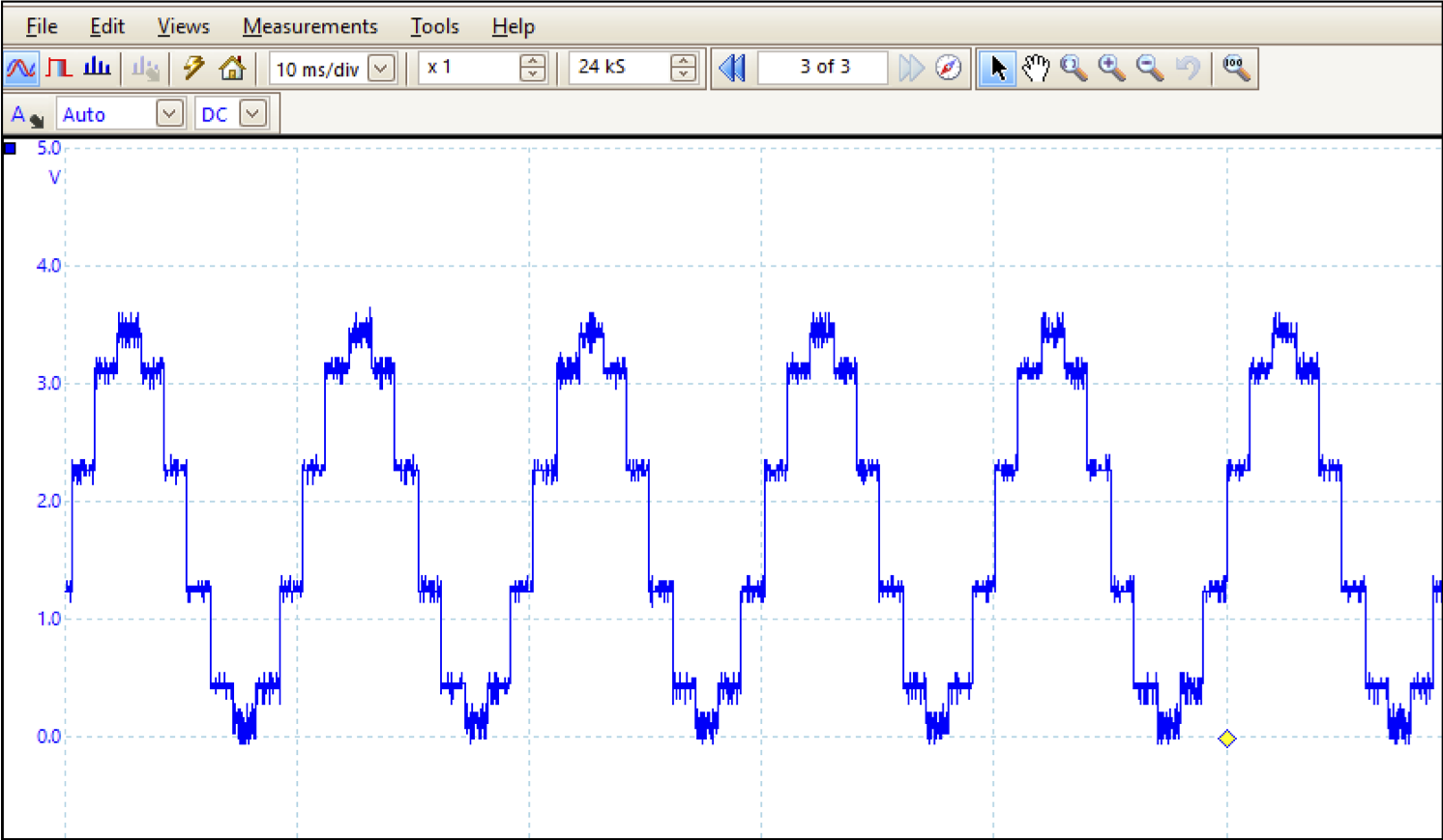
Below is the output viewed on a scope. Two things are more clearly visible here:
- Quantisation – the steps are clearly visible here. We sometimes call this an “artifact” created by the electronics and/or software
- Noise – for each step, you can visibly see noise superimposed on top of the waveform. Noise is not created by the software, but might be a property of the electronics and needs to be reduced. Often it is interference from other electrical systems.
This is clearly not a perfect 100Hz sinusoid, so is not going to sound like one if played through an amplifier and speaker. There are some steps we could (and probably should) now take:
- Ensure “de-coupling capacitors” are used on the power-supplies of all switching devices. This maintains a smooth DC power supply for each device .
- “Filter” the output to make it smoother. For this, we need additional electronics.
You can (and will) use mathematics to better predict and understand the quantisation noise, and design electronic “filters” to significantly reduce unwanted components. In this application, they are known as “anti-imaging” filters. Strictly speaking, we should also use similar filters for the ADC as well.
REMEMBER to replace JP6 when you’ve completed the SPI tasks.
[contact-form][contact-field label=”Name” type=”name” required=”true” /][contact-field label=”Email” type=”email” required=”true” /][contact-field label=”Website” type=”url” /][contact-field label=”Message” type=”textarea” /][/contact-form]