Defining a Component
When you create a component, you specify the entity and at least one architecture.
- The entity defines the inputs and output signals.
- The entity describes the logical relationship between the input and output signals.
You can think of an entity as the description of a device, as viewed from the outside. For example:
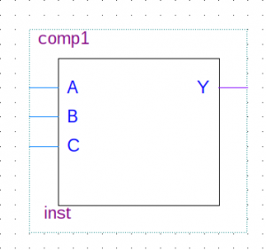
library ieee;
use ieee.std_logic_1164.all;

-- Component 1 - very simple device that performs a logical OR on three single bit inputs
entity comp1 is
 port( A: in std_logic;
 B: in std_logic;
 C: in std_logic;
 Y: out std_logic
);
end comp1;
The highlighted line is the start of the entity declaration.
- The name of the entity is comp1
- This entity has a single architecture inst1
We can represent this component visually as follows:
Below the entity is the architecture that contains the logic
--This component only has one architecture
architecture inst1 of comp1 is
begin
 Y <= A or B or C;
end inst1;
We could use this component in a design, synthesise it and test on real hardware. However, it is advisable (where possible) to simulate it first. Tools included with Altera Quartus II allow us to do this using either:
- Vector Waveform File (simulation)
- SignalTap on Hardware
- Running a “Test Bench” in ModelSim (simulation)
This article is concerned with the latter approach as it provides a very rich array of testing facilities that would be hard to replicate on hardware.
Writing a Testbench
A testbench is simple a VHDL component with no input or output signals. All signals are in fact internal. This might seem strange at first, as you will see, a test-bench is never intended to be run on hardware – it is purely for simulation and test. What’s more, there are conditions you can detect in simulation that would be very hard to spot in hardware (as we will see later).
Let’s now look at a simple test bench for the comp1 component
library ieee;
use ieee.std_logic_1164.all;
use ieee.numeric_std.all;

entity comp1_test is
--NOTHING TO SEE HERE
end comp1_test;

architecture inst1 of comp1_test is

--Declare components
 component comp1
  port( A: in std_logic;
        B: in std_logic;
        C: in std_logic;
        Y: out std_logic);
 end component;

 --Declare signals
 signal AA : std_logic := '0';
 signal BB : std_logic := '0';
 signal CC : std_logic := '0';
 signal YY : std_logic := '0';


begin
 --Instantiate a component of type comp1
 u1: comp1 PORT MAP (
 A => AA,
 B => BB,
 C => CC,
 Y => YY
 );

comp1_process:
 process
  variable count : std_logic_vector(2 downto 0);
 begin
  --Exhaustive test
  for idx in 0 to 7 loop
   --Convert integer idx to std_logic
   count := std_logic_vector(to_unsigned(idx,3));

   --Assign internal signals to the individual bits of count
   AA <= count(0);
   BB <= count(1);
   CC <= count(2);

   --Wait for 20ns (also prompts signals to update)
   wait for 20 ns;
  end loop;

  --End of test is to wait forever
  wait;
 end process;

end inst1;
Let’s now break this down into sections to help understand what is happening.
Entity
All test bench components have an empty entity, as shown here
entity comp1_test is
 --NOTHING TO SEE HERE
end comp1_test;
Remember that we are creating an independent component comp1_test (comp1_test.vhd) to test the component comp1 (comp1.vhd). Whereas comp1.vhd might feature in a real design, comp1_test.vhd will not.
Architecture
The code to perform the test is written in the architecture of the testbench. The principle is to use structural VHDL to do the following:
- declare all components and signals (before the begin statement)
- instantiate the component under test.
- connect its inputs and outputs to internal signals
- stimulate those internal signals
- check the output agrees with the expected results
Let’s look at each aspect in turn.
Declare the component under test
Before we start, we must declare the component we wish to test in the architecture of the test bench (before the begin statement). Note that it is assumed that the component name is the same as the filename, and that it is in the same working folder.
component comp1
 port( A: in std_logic;
       B: in std_logic;
       C: in std_logic;
       Y: out std_logic);
end component;
This tells the VHDL compiler about the component and it’s input / output signal names and types. Note that signal names must match the original (I tend to copy and paste the port declaration from the original file).
Declare internal signals
Next we need some signals to stimulate (set and reset over time) and monitor. These will eventually be connected to the inputs and outputs of the component under test.
 --Declare signals
 signal AA : std_logic := '0';
 signal BB : std_logic := '0';
 signal CC : std_logic := '0';
 signal YY : std_logic := '0';
Note that these signals are only visible to the architecture body of the test bench. I’ve initialized these signals to ‘0’ at the start of simulation as the device under test has no reset capability. This is entirely optional.
Instantiate a component under test
Imagine we were working with a schematic editor. When we place a component on the sheet, it is said that we create an instance of that component with a label Un (where n is an integer). That instance is independent of all others, and internally, has its own state (output state of all its logic gates).
The VHDL equivalent of placing a component on a schematic sheet is to instantiate it as follows (after the begin statement):
 --Instantiate a component of type comp1
 u1: comp1 PORT MAP (
   A => AA,
   B => BB,
   C => CC,
   Y => YY
 );
What this means is:
- A component u1 shall be created
- This component being instantiated has the entity name comp1 (as declared above)
- The input signals of this entity A,B and C are connected to signals AA, BB and CC respectively
- The output signal Y is connected to the signal YY
Put briefly, any changes made to the internal signals AA, BB and CC are applied to the inputs of component u1. Any changes in the output of this component will be observable via the signal YY.
Create at least one process block
The centre piece of any testbench is a process block. In this process block, you generate tests by asserting the test signals (AA,CC,BB) while observing the output (YY).
The general structure is as follows:
process
   --declarations
begin
   --assert the input signal(s)
   --wait, then check the output signal(s)

   --End of test is to wait forever
   wait;
end process;
This test bench is going to perform (almost) exhaustive testing, that is, it will present every possible valid binary state to the input of the component being testing. Let’s look at this specific example.
process
	variable count : std_logic_vector(2 downto 0);
begin
	--Exhaustive test
	for idx in 0 to 7 loop
		--Convert integer idx to std_logic
		count := std_logic_vector(to_unsigned(idx,3));

		--Assign internal signals to the individual bits of count
		AA <= count(0);
		BB <= count(1);
		CC <= count(2);

		--Wait for 20ns (also prompts signals to update)
		wait for 20 ns;
	end loop;

	--End of test is to wait forever
	wait;
end process;
Some key points to note from this:
- A for-loop is set up to present input values from 0..7 (000b..111b).
- The variable idx has the type integer, so this is converted to std_logic_vector
- Bit 0 of count is assigned to the internal signal AA (which in turn is connected to input A of the component being tested). Similar patterns for used for Bits 1 and 2
- A wait of 20ns is then added for each iteration of the loop
The last point is critical if we wish to observe any changes in the output. Remember that unlike variables, signals are not updated until the end of a process block or until a wait statement is encountered. This is because a process block is said to update in zero time unless a wait statement is added.
Note that wait cannot be synthesised. Don’t be tempted to try to synthesise delays in VHDL using a wait statement! It is only for simulation.
Once the loop has completed, the process block waits forever. If all process blocks are waiting indefinitely, the simulation ends.
Checking the Output with ModelSim
Ok, so that’s covered the stimulus of the component inputs, but what about the output? So far, little reference has been made to the output. There are a few options available, starting with graphical inspection in ModelSim.
It’s a lot quicker to show than to write, so watch the following video. Make sure you select 1080p (HD) as some of the fonts are small.
While you are here, I suggest you also watch the following video which explains how to use project files.
Next, we will look at testing architectures with multiple architectures.