In the previous section, we looked at testing a single component with a single architecture. We are now going to look at how to test multiple architectures.
Any given entity can have one or more architectures. There are a number of reasons why you might do this, including:
- Some architectures may be optimised for space, while others are chosen for speed
- Some may use different styles of VHDL – the first might use behavioural VHDL to get the function quickly defined. You might then add another that uses structural VHDL. As you develop this, you can compare outputs to help test your second design.
- Some may exhibit different timing characteristics – such as hazards
- You might create additional architectures with additional test facilities
Component with Two Architectures
Continuing with the theme from the previous section, we now modify the component to add an additional architecture. The intention is that this second architecture is functionally identical to the first (I’ve simply applied DeMorgan’s theorem). However, to make an important point, I’ve purposely left an error in the second architecture.
Here is the modified component with the second architecture included:
library ieee;
use ieee.std_logic_1164.all;
--use ieee.std_logic_unsigned.all;

-- Component 1 - very simple device that performs a logical OR on three single bit inputs
entity comp1 is
port(  	A:	in std_logic;
	B:	in std_logic;
	C:	in std_logic;
	Y:	out std_logic
);
end comp1;

--This component has two architecture
architecture v1 of comp1 is
begin
	y <= A or B or C;
end v1;

--This second version is supposed to be functionally equivalent
--HOWEVER, there is a bug
architecture v2 of comp1 is
begin
	y <= (not A) and (not B) and  (not C);
end v2;
v1 and v2.Testbench
We are now going to instantiate both versions of the comp1 component and compare their outputs in a testbench. The VHDL code is shown below
library ieee;
use ieee.std_logic_1164.all;
use ieee.numeric_std.all;
--use ieee.std_logic_unsigned.all;
--use std.textio.all;

entity comp1_test is
end comp1_test;

architecture inst1 of comp1_test is

	--Declare signals
	signal AA : std_logic;
	signal BB : std_logic;
	signal CC : std_logic;
	signal Y1 : std_logic;	--output for version 1
	signal Y2 : std_logic;	--output for version 2

begin
	--Instantiate v1 of the component type comp1
	u1: entity work.comp1(v1) PORT MAP (
		A => AA,
		B => BB,
		C => CC,
		Y => Y1
	);

	--Instantiate v2 of the component type comp1
	u2: entity work.comp1(v2) PORT MAP (
		A => AA,
		B => BB,
		C => CC,
		Y => Y2
	);

	comp1_process:
	process
		variable count : std_logic_vector(2 downto 0);
	begin
		--Exhaustive test
		for idx in 0 to 7 loop
			--Convert integer idx to std_logic
			count := std_logic_vector(to_unsigned(idx,3));

			--Assign internal signals to the individual bits of count
			AA <= count(0);
			BB <= count(1);
			CC <= count(2);

			--Wait for 20ns (also prompts signals to update)
			wait for 20 ns;
		end loop;

		--End of test is to wait forever
		wait;
	end process;

end inst1;
- The component declaration has been dropped (it’s optional in this case)
- The syntax for instantiation now has changed.
u1: entity work.comp1(v1) PORT MAP (
		A => AA,
		B => BB,
		C => CC,
		Y => Y1 );
entity keyword, followed by a more explicit reference to the component under test: work.comp1(v1). The second instance is similar:u2: entity work.comp1(v2) PORT MAP ( A => AA, B => BB, C => CC, Y => Y2 );
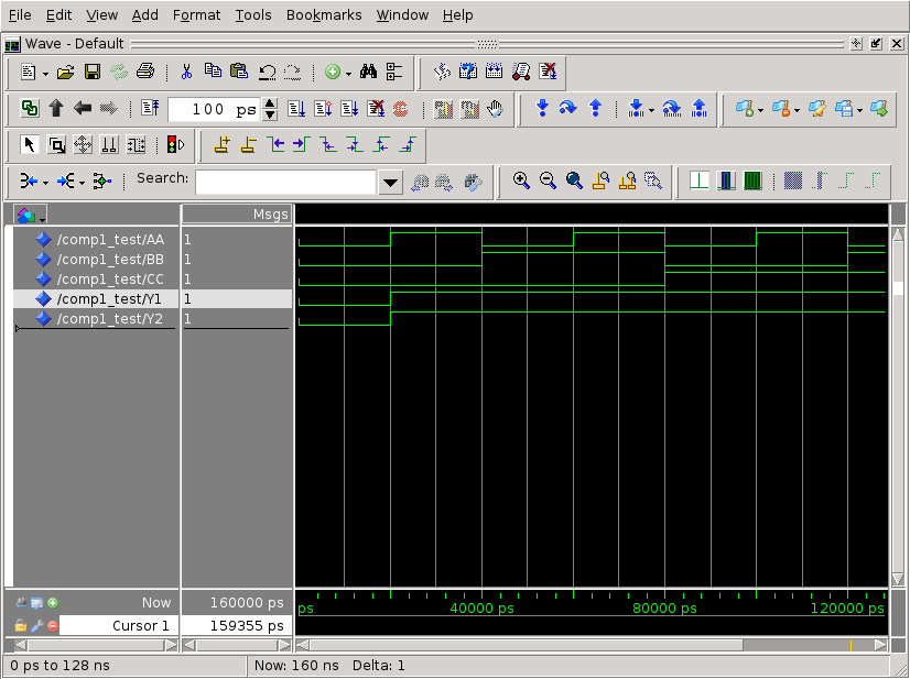
u2. It’s as if a second component has added to a schematic and wired to the same input signals (AA,BB and CC). Note however that the outputs are connected to two separate signals, Y1 and Y2. We can now visually compare these signals with ModelSim. The output of the testbench is shown below: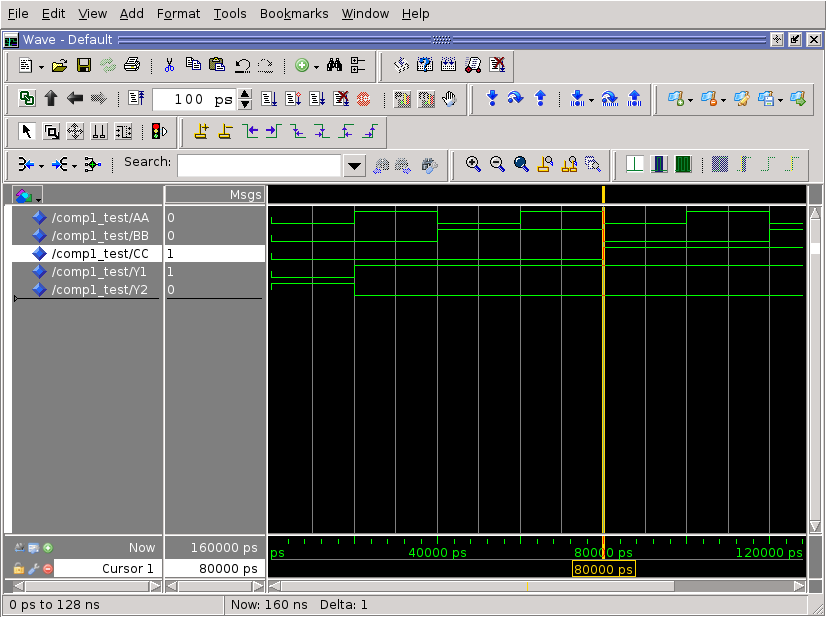
You can see from the figure above that the outputs differ, and that one is the logical inverse of the other. I have indeed forgotten to invert the result when I performed DeMorgan’s.
Corrected Version
The corrected v2 architecture is shown below: