The majority of sequential logic systems use a shared clock to synchronise outputs. We say such systems are “synchronous”. One of the most fundamental building blocks of a synchronous systems if the D-Type Flip-Flop.
This is defined in the following VHDL:
library ieee;
use ieee.std_logic_1164.all;

--D-Type Flipflop primitive
entity dff_primitive is
port(  	D:	in std_logic;
	CLK:	in std_logic;
	Q:	out std_logic
);
end dff_primitive;

--This component has two architecture
architecture v1 of dff_primitive is

begin
	process(CLK)
	begin
		--Update Q on the rising edge of CLK
		if rising_edge(CLK) then
			Q <= D;
			-- The absence of an else will result in a latching behviour
		end if;
	end process;
end v1;
In words, the output Q is latched to the input value D on the rising edge of the clock CLK Note that this is edge triggered, and NOT level triggered. Special edge detection circuitry is is used in synthesis.
Note how the rising_edge function is used in this example. This function only returns a boolean true when the signal changes from a low value (‘0’ or ‘L’) to a high value (‘1’ or ‘H’). It does not return true for a transition from ‘U’ to ‘1’.
Testing
To test a D-Type Flip-Flop requires the generation of a clock. Ideally, we should also examine the outputs of the D-Type Flip-Flop for specific input sequences.
Let’s look at a testbench to test the following:
- Latching a ‘0’ input
- Latching a ‘1’ input
- Ignoring input changes between clock edges
For clarity, this will be limited to functional testing and will ignore timing such as set-up and hold-time violations.
library ieee;
use ieee.std_logic_1164.all;
use ieee.numeric_std.all;
--use ieee.std_logic_unsigned.all;
--use std.textio.all;

entity dff_test is
end dff_test;

architecture v1 of dff_test is
	--Declare signals
	signal D_INPUT     : std_logic;
	signal CLK_INPUT   : std_logic := '0';
	signal Q_OUTPUT    : std_logic;
	constant Tclk      : time  := 50 ns;
	constant Tsim	   : time  := 1000 ns;

	--Simple procedure to check the level of a signal
	procedure checkOutput(expected : std_logic) is
	begin
		assert(Q_OUTPUT = expected)
			report "DFF output incorrect"
			severity error;
	end checkOutput;

	--Simple procedures to wait on clock edges
	procedure waitForClockToFall is
	begin
		wait until (CLK_INPUT'EVENT and CLK_INPUT = '0');
	end waitForClockToFall;

	procedure waitForClockToRise is
	begin
		wait until (CLK_INPUT'EVENT and CLK_INPUT = '1');
	end waitForClockToRise;

begin
	--Instantiate v1 of the component type dlatch_primative
	u1: entity work.dff_primitive(v1) PORT MAP (
		D   => D_INPUT,
		CLK => CLK_INPUT,
		Q   => Q_OUTPUT
	);

	clock_process:
	process
		variable t : time := 0 ns;
	begin
		loop
			t := t + Tclk;
			wait for Tclk;
			CLK_INPUT <= not CLK_INPUT;
			exit when t >= Tsim;
		end loop;
		wait;
	end process;

	main_process:
	process
		--Declarations here
	begin
		--Set on falling edge of clock so signal is stable on rising
		waitForClockToFall;

		-- latching a zero on the output
		D_INPUT <= '0';

		--Check output
		waitForClockToRise;
		checkOutput('0');

		--test latching a one
		waitForClockToFall;
		D_INPUT <= '1';

		waitForClockToRise;
		checkOutput('1');

		waitForClockToFall;
		checkOutput('1');

		--show that input is ignored elsewhere
		D_INPUT <= '0';
		wait for (Tclk / 10);
		checkOutput('1');

		D_INPUT <= '1';
		wait for (Tclk / 10);
		checkOutput('1');

		D_INPUT <= '0';
		wait for (Tclk / 10);
		checkOutput('1');


		D_INPUT <= '0';
		waitForClockToFall;
		waitForClockToRise;
		checkOutput('0');


		--End of test is to wait forever
		wait;
	end process;

end v1;
Before we examine this in more detail, let’s look at the simulation output:
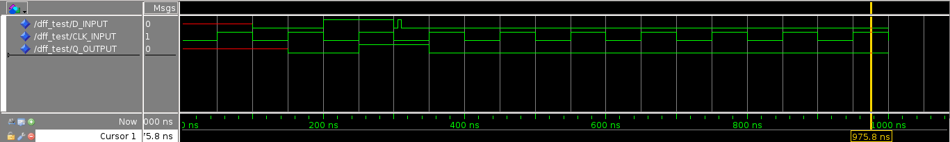
There are some points of interest:
- At time < 100ns, the input is undefined.
- At time < 150ns, the output is undefined (suggesting this device may need a reset input)
- At times 150ns and 350ns there is a rising edge of clock, and a correct output transition to value ‘0’. This is shown to latch
- At time 250ns there is a rising edge of clock, and a correct output transition to value ‘1’. This is shown to latch
- At time 300ns and shortly after, there are some perturbations in the input. These are shown to be correctly ignored
This is not exhaustive, but provides good coverage for illustrative purposes. Let’s now look more closely at the test-bench where we meet some new concepts:
The component under test is instantiated as we’ve done before:
u1: entity work.dff_primitive(v1) PORT MAP ( D => D_INPUT, CLK => CLK_INPUT, Q => Q_OUTPUT );
Therefore, we see that we should stimulate the D_INPUT and CLK_INPUT signals, while observing the Q_OUTPUT signal.
Separation of Concerns
Note there are two process blocks in the testbench, clock_process which stimulates the CLK_INPUT signal and main_process which stimulates (and checks) the Q_OUTPUT signal.
- They are separated to help simplify the structure
- The run concurrently
- Each will stimulate a unique set of signals
It is good practise to factor out a task in this way. Each process block has a distinct responsibility.
Clock Process
The clock process has the single task of generating a clock signal for a defined period of time. In this example, the loop – end loop mechanism is used. We could equally have used a for-loop or some other approach.
	clock_process:
	process
		variable t : time := 0 ns;
	begin
		loop
			t := t + Tclk;
			wait for Tclk;
			CLK_INPUT <= not CLK_INPUT;
			exit when t >= Tsim;
		end loop;
		wait;
	end process;
The highlighted lines show how the clock signal is toggled every 50 ns. Note how a variable is used to keep track of time-elapsed, and that the loop exists once Tsim ns have elapsed. To make the code more readable, two constants are defined in the testbench architecture:
constant Tclk : time := 50 ns;
constant Tsim : time := 1000 ns;
Main Process
Given that the clock signal is now managed elsewhere, the main process simply needs to stimulate the D_INPUT signal at the correct times and to check the output signal Q_OUTPUT . Here is a sample taken from this process:
--Set on falling edge of clock so signal is stable on rising
waitForClockToFall;

-- latching a zero on the output
D_INPUT <= '0';

--Check output
waitForClockToRise;
checkOutput('0');
The procedure is as follows:
- The input signal D_INPUT is forced to logic ‘0’ after the fall of the clock edge (thus ensuring the input is stable for half a clock period before the rising edge)
- The simulation then waits for a rising edge of the clock CLK_INPUT
- The output signal Q_OUTPUT is checked immediately (there is no propagation delay in a functional simulation).
Note that three VHDL procedures were used to reduce code repetition and improve readability. The first waits for a falling clock edge.
procedure waitForClockToFall is
begin
	wait until (CLK_INPUT'EVENT and CLK_INPUT = '0');
end waitForClockToFall;
This is invoked by simply writing waitForClockToFall in the testbench. The second is similar, and waits for a rising clock edge:
procedure waitForClockToRise is
begin
	wait until (CLK_INPUT'EVENT and CLK_INPUT = '1');
end waitForClockToRise;
Finally, the checkOutput procedure is defined. This is somewhat different from the preceding two examples as it takes an input parameter. Note that it is possible to have more than one parameter (each is separated by a semi-colon).
procedure checkOutput(expected : std_logic) is
begin
	assert(Q_OUTPUT = expected)
		report "DFF output incorrect"
		severity error;
end checkOutput;
Automatic Testing with assert
The last example used the all-important assert function to test for a specific condition. Where this condition is found to be false, then a message is written to the terminal. The severity is set as note , warning , error or failure .
When we run this simulation, we discover there are two errors reported!
# ** Error: DFF output incorrect
# Time: 150 ns Iteration: 1 Instance: /dff_test
# ** Error: DFF output incorrect
# Time: 250 ns Iteration: 1 Instance: /dff_test
This might seem strange as the simulation, the output looked correct. Watch the following video to see how this is resolved.
The issue was that the output signal Q_OUTPUT was being observer too quickly for the simulator! The solution used in this example was to change the waitForClockToFall and waitForClockToRise procedures to wait 1ps beyond the clock edge.
procedure waitForClockToFall is
begin
	wait until (CLK_INPUT'DELAYED(1 ps)'EVENT and CLK_INPUT = '0');
end waitForClockToFall;

procedure waitForClockToRise is
begin
	wait until (CLK_INPUT'DELAYED(1 ps)'EVENT and CLK_INPUT = '1');
end waitForClockToRise;
The attribute DELAYED is useful for observing and/or waiting on delayed versions of signals. Of course, if we were to model timing, such as propagation delay, this technique could be used as well.