In this section we look at interfacing with the analogue world using mbed. You will use a simple potentiometer to generate analogue voltages, and measure that voltage using an Analogue to Digital Converter (ADC) to perform sampling. Analogue signals suffer problems with noise and uncertainty. Analogue filters are used to prevent a phenomena known as aliasing when sampling a signal. For simple threshold detection, hysteresis is introduced to manage signal noise and avoid output jitter.
We then look at digital to analogue conversion, using both pulse-width modulation (crude, but useful for motor speed control) and a Digital-to-Analogue Converter (DAC) for more precise applications.
The mechanisms for conversion in mbed are very simple.
What is more important are the techniques for determining an accurate sampling rate and reducing aliasing noise.
For accurate sampling, we will use the Ticker component to generate interrupts driven by a hardware timer.
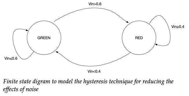
For a simple threshold detection task such as this, we might can use “hysteresis” to address the problem of noise.
Hysteresis
This is a technique for reducing (and sometimes effectively eliminating) the effects of noise when detecting if a signal crosses a threshold. Consider the figure below. This shows an analogue signal  varying with respect to time
  .
.
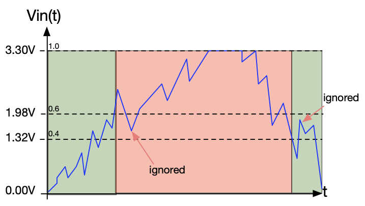
Consider the example of the blue waveform in the figure. The signal is below the lower threshold at  , so the output is GREEN. Hysteresis works as follows:
- In the GREEN (lower) state, the system will only switch to the RED state when the signal crosses above the upper threshold of 1.98V.
- Once in the RED (upper) state, the system will now only switch to the GREEN state when the signal crosses below the lower threshold of 1.32V.
As the signal rises above the upper threshold of 1.98V, the output state changes state to RED. Note that signal noise causes the signal to dip down below 1.98V shortly after, but that is ignored as it is still above the (revised) lower threshold.
Later, the signal drops below the lower threshold causing a state change. Again due to noise, the signal rises above the lower threshold but is once again ignored as it does not exceed the upper threshold.
For this example, the noise margin is 
A device that employs this technique in this way is known as a Schmitt Trigger https://en.wikipedia.org/wiki/Schmitt_trigger
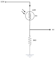
Light Dependent Resistor (LDR)
In this task we are going to use a new passive component, the Light Dependent Resistor (LDR).
![]()
![]()
The resistance decreases as light is increased**. In the dark, resistance in the order of  can be achieved. In very bright light, a resistance in the order of 100s of are
  typical.
**Note – The resistance is also partly dependent on temperature, so these devices are not ideally suited to accurate measurement or instrumentation. https://en.wikipedia.org/wiki/Photoresistor
Used in a potential divider circuit, a simple light-to-voltage can be created, as shown:
Sampling with a polling loop
I the next task you will sample the light level using a simple polling loop.
#include "mbed.h"

#define kRED    (1 << 2)    //4
#define kYELLOW (1 << 1)    //2
#define kGREEN  (1 << 0)    //1
#define kALL (kRED | kYELLOW | kGREEN)

//Global objects
BusOut binaryOutput(D5, D6, D7);
DigitalIn SW1(D3);
DigitalIn SW2(D4);

AnalogIn POT_ADC_In(A0);
AnalogIn LDD_ADC_In(A1);
float fPOT, fLDR = 0.0;

//Main function
int main() {

   while(1) {

      //Read ADC
      fPOT = POT_ADC_In;
      fLDR = LDD_ADC_In;

      //Write to terminal
      printf("POT = %6.4f\tLDR = %6.4f\n", fPOT, fLDR);

      if (fLDR > fPOT) {
         binaryOutput = 0;      //Binary 000
      } else {
         binaryOutput = kALL;   //Binary 111
      }

      //Wait
      wait(0.1);

   } //end while(1)
} //end main
Note: In effect, you are using the POT to set the threshold for the light sensor.
The time around the loop, and hence the sampling interval is dependant on the wait statement + time to execute the loop body.
The sampling rate is therefore not constant. The time between each sample read depends on the execution time of the code each time around the loop. This varies for a number of reasons:
- The conditional statements (if) causes branches in the code which take different times.
- Every time the code is modified, the time is likely to change.
- If the compiler “optimisation settings” are changed, or the compiler is updated, this will again impact on code execution time.
Some Perspective
If you are not concerned with a consistent sampling rate (measured in samples/s or Hz), then the simplicity of the code above is in itself an advantage over other more complex approaches. The power efficiency is something that might need to be checked of course.
There are many Digital Signal Processing (DSP) applications that do rely on samples being acquired at strictly even time intervals. For such applications, the approach above is naive.
The degree to which the sampling interval varies is known as jitter. We try and minimise jitter for DSP applications, although it can never be eliminated (even crystal clocks frequencies will have some variance).
One way to address achieve a low jitter is to use a timer interrupt.
Sampling with Interrupts
A technique used by nearly every microprocessor and micro-controller to cause a branch in execution upon the occurrence of a hardware or software event.
There are two broad categories:
Hardware interrupt – whereby the code is forced to branch when a hardware device (e.g. serial interface, GPIO input, timer, ADC etc..) flags that an event has occurred.
Software interrupt – whereby the code is forced to branch when a software event occurs, such as a divide by zero or a trap instruction. It is still driven by hardware, but the code must be running for this to occur (and not in sleep mode).
When an interrupt occurs, a few things typically occur:
- context save – whereby CPU registers are preserved, typically on the current function stack
- return address is preserved
- the execution automatically branches to a specified function, known as an “Interrupt Service Routine” (ISR).
- upon completion, the return address is reinstated and the registers are restored, (as if nothing had occurred).
The ISR may well have modified some memory, or interacted with the state of the hardware. Such effects are sometimes known as “side effects”. The programmer has to be very careful not to cause data corruption as a consequence.
As you may already know, interrupts are commonly used to achieve a timely response to external events. For example:
- when a timer reaches its target value, a branch is forced so that a function executes at precise intervals. This is sometimes used in sampling.
- when a serial interface receives some data, an interrupt is forces the system to branch and read the data (and prevent data loss).
- if power begins to fail, an on-chip “brown-out” detection can generate an interrupt to put the system in a safe state before shutting down (assuming there is enough time to react of course).
Nesting
Some devices allow interrupts to interrupt (aka preempt) each other. They typically use a numerical priority scheme to determine which interrupts take precedence. It can be quite challenging to design real-time systems using such as scheme.
Power Saving
The CMOS logic used to build modern micros only consumes power when it is switching state. When a CPU has nothing to do, simply cycling inside a loop is therefore wasteful of power, as is powering unused peripherals.
Most micros can switch of peripherals that are not required (in the case of the ARM series of devices, the clocks are gated off to prevent them switching). Furthermore, most support idle modes, whereby the code execution logic is suspended in a low power state. It is only interrupts that can wake the CPU from the low power state to service a request. When all requests have been serviced, the CPU can return to an idle mode.
It is probably worth pointing out that without interrupts, the CPU cannot escape idle mode.
Interrupt Safety
Many functions, including printf and scanf, are not safe to use within an interrupt service routine. Furthermore, many of the mbed objects are not interrupt safe either. Always check the documentation before using a function or class in an interrupt.
As you can see, using interrupts can be challenging and great care is needed to avoid data corruption.
Using the Mbed-os Ticker
In mbed, there is a component called a Ticker. This object maintains a hardware timer. When that timer reaches a certain value, an interrupt occurs, and branches to the function you specify. This function should take no arguments and return no data. For example:
void doISR() {
   state ^= 1;
}
It is probably best to give an example to explain this.
#include "mbed.h"
DigitalOut myled(LED1);
Ticker t;
static int state = 0;
void doISR();

int main() {
   t.attach(doISR, 2);
   myled = 0;

   while(1) {

      sleep();    //At is says

      //At this point, the ISR has run
      myled = state;

      if (state == 0) {
         printf("LED OFF\n");
      } else {
         printf("LED ON\n");
      }
      wait_us(9000);  //Give time for printf to finish!
   }
}

void doISR() {
   state ^= 1;  //TOGGLE
}
First we create an instance of the Ticker object
Ticker t;
Now we specify what function it shall call, and how often.
t.attach(doISR, 2);
The first parameter is the name of the function. In fact, this is actually the address of the function in program memory, but that is a detail right now. Sometimes you see it written like this:
t.attach(&doISR, 2);
This example will cause the function doISR to run every 2 seconds (assuming another interrupt of equal or higher priority is not already running). The Ticker does some “C++ magic” and is said to “encapsulate” a hardware timer. C++ is covered in level 6. If you don’t understand this, don’t worry.
Note: The first parameter is an example of a function pointer. The prefix & means “address of”. This is actually optional for function pointers. The interval between interrupts is specified by the second parameter (in seconds).
What might surprise you is the first statement in the while loop, which is:
sleep();
This does what it says: it puts the CPU into a sleeping state, sometimes known as idle mode. During this state, the CPU is idle but the hardware timer is still running. The hardware timer is a separate piece of electronics inside the micro-controller which genuinely runs in parallel with the CPU (you might say this is the most genuine form of multi-tasking).
When 2 seconds have elapsed, the CPU is woken up and the doISR function is called for you (by the NVIC hardware). All this function does is toggle a variable between
0 and 1 as follows:
void doISR() {
   //Toggle 0 to 1, or 1 to 0
   state ^= 1;
}
The code in the while loop can then resume beyond the sleep() function, which is to update the LED output and write to the terminal.
myled = state;

if (state == 0) {
   printf("LED OFF\n");
} else {
   printf("LED ON\n");
}

//Give time for printf to finish!
wait_us(9000);
When everything is done, the code loops and the CPU returns to the sleep mode, until the ticker wakes it again. This saves a considerable amount of power.
Question: Note that printf is in main, and not in the ISR. Why not just put all the code in the ISR?
Note that printf is also followed by a delay of 9ms. This is because printf communicates with a serial interface, and the serial interface uses interrupts. The delay is intended to wait until all characters are sent. Without this delay, the CPU would be brought out of sleep by the serial port interrupts!
 Bytes/second. Therefore each character takes
  seconds to complete.
Allowing for 10 characters, we need to wait for 9ms until all the characters have been send and the serial interrupts have completed. This assumes the device at the other end is ready to receive the data of course.
Key Observation
The interrupt service routine runs once every 2 seconds. The frequency is fixed, and is independent of the code in the main function, compiler settings etc..
We can say that the ISR is “deterministic” (fully predictable in time).
This example is a rather special case. We have designed this system such that the CPU is always in an idle mode when the interrupt occurs. Therefore, we know where the program has got to when the interrupt occurs (sleep statement).
Please note that this is not generally the case with interrupts, so do not extend this pattern into other applications.
Question: Why would this software pattern not be appropriate for a system with a single interrupt driven by a push switch?
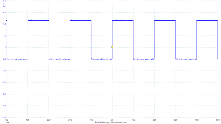
You should see a very regular and stable waveform as shown below.
Accurate Sampling with a Timer Interrupt
We are using the Mbed-os framework (set of C++ objects) to perform rapid development of embedded software. We will now sample an analogue input using an on-chip Analogue to Digital Converter (ADC) and the AnalogIn component. Note the the default behaviour is to return a value a fractional value of type float, scaled between 0.0 and 1.0. In this task, we read the raw integer value.
#include "mbed.h"

//Function prototype
void doSample1Hz();

//Global objects
Serial pc(USBTX, USBRX);
AnalogIn POT_ADC_In(A0);
DigitalOut led(LED1);

//Shared variables
volatile static unsigned short sample16 = 0;

//The ticker, used to sample data at a fixed rate
Ticker t;

//Main function
int main()
{
    //Set baud rate to 115200
    pc.baud(115200);

    //Set up the ticker - 100Hz
    t.attach(doSample1Hz, 1.0);

    while(1) {

        //Sleep
        sleep();

        //READ ADC as an unsigned integer.
        //Shift right 4 bits (this is a 12bit ADC) & store in static global variable
        sample16 = POT_ADC_In.read_u16() >> 4;

        //Display the sample in HEX
        pc.printf("ADC Value: %X\n", sample16);
        //Wait for 20 characters to clear
        wait(0.0014);

    } //end while(1)
} //end main

//ISR for the ticker - simply there to perform sampling
void doSample1Hz()
{
    //Toggle on board led
    led = !led;
}
The sampling is performed by the line:
sample16 = POT_ADC_In.read_u16() >> 4;
The member function read_u16() returns a 16 bit integer, high-bit aligned. The device we are using is 12 bit ADC, so the result always has four zero in the least significant bit positions. This is why the result is shifted right 4 bits.
Important Notes:
This example illustrates an important design pattern which works (only) for very simple single-interrupt problems.
- The main function is first allowed to sleep (saving power)
- When the timer hits its target value, the CPU is woken and execution branches to the ISR
- It is assumed the timer interrupt is the ONLY interrupt that can fire during the sleep state
- The ISR will then run the time critical code to completion – this is typically kept as short as possible.
- When the ISR exits, the main function is then allowed to resume, until it loops and sleeps again.
- Note once again the delay after the
printfstatements (allows time for all serial port interrupts to complete)
Note how in this specific (and simple) example, main and the ISR are time synchronised. This is because of sleep() and the fact that we only have a single timer interrupt firing during the sleep phase.
- We avoid race conditions because we know the CPU is always sleeping when the interrupt occurs
- Therefore, there is no danger of preempting the reading of
sample16in main
In general, interrupts are asynchronous, so this pattern would not work. For example, using InterruptIn to detect the press of a switch is asynchronous, and unlike a Timer, we can’t predict when it will happen or how frequently.
In general, interrupt driven code can become much more complicated so we will need further strategies to avoid race conditions if our task is to scale.
Digital to Analogue Conversion (Analogue Output)
This is section, we look at ways to output analogue signals. For this we use two techniques:
- Pulse Width Modulation (PWM)
- Digital to Analogue Converter (using the on-chip DAC).
Pulse Width Modulation (PWM)
Pulse Width Modulation or PWM is a simple technique used to control an output (mean DC) voltage. The technique is commonly used in control systems, including the control of DC motors, in part because it does not require the use of linear DC amplifiers. See the glossary entry on the H-Bridge if you want to know about DC motor control.
TASK – you should first familiarise yourself with the glossary entry on PWM
PWM is simple to implement. We can use either a Timer and a GPIO pin (DigitalOut) or one of the dedicated PWM outputs (not all pins support PWM).
Pulse Width Modulation (PWM) with Timers
In this task we will implement PWM using a a simple timer (mbed Ticker).
#include "mbed.h"

//Time period
#define T 0.001

//Mark-Space Ratio
#define R 0.1

//Mark and Space times
#define Tmark (R*T)
#define Tspace ((1.0-R)*T)

DigitalOut onboardRedLed(LED3);
DigitalOut redLED(D7);

int main() {
   printf("\nWelcome to ELEC143\n");

   while (1) {
      redLED = 0; //Space
      onboardRedLed = 0;
      wait(Tspace);
      redLED = 1;	//Mark
      onboardRedLed = 1;
      wait(Tmark);
   }
}
Note that the wait function is blocking. We assume it does not use the CPU idle mode and simply spins, waiting for a timer to reach a specified value. This approach does not scale well as will be revealed in the next task 5.2.2.
Note – do not spend too much time on the next task as it’s supposed to be “awkward”. It is intended to make a point! A solution is also available.
You may have noticed already that this is rather cumbersome. There are many ways to try and solve this problem. I have provided one solution that uses timer interrupts (although even this is not perfect).
What you might find is that your solution does not “scale” beyond two LEDs. One of the fundamental problems here is that the wait statement is “blocking” (you cannot do anything else unless you use an interrupt).
There are a number of elegant solutions. Timers are one possibility (as I have used), but you might want to reserve those timers for other tasks. I’ve kept the interrupt routines as short as possible to avoid latency issues (in the event two overlap in time such that one has to wait for the other to finish).
Luckily, PWM is a common requirement and this problem was recognised a long time ago, and this microcontroller comes with PWM controllers built in! These controllers have their own timers and logic to control the output, so all run independently in parallel.
Remember: a single core microcontroller can only really execute one instruction at a time. Any attempt at multitasking is always an illusion and often comes with compromises.
Look at the code below to see how simple it is to use a PWM in mbed on this device.
#include "mbed.h"
DigitalOut led1(LED1);
PwmOut pwm(D6);

int main() {
   pwm.period_us(10);
   pwm = 0.5;

   while(1) {
     wait(0.5);
     led1=!led1;
    }
}
Task: Use an oscilloscope to observe the signal on D6.
This code is very simple. This is because we are using the PwmOut type object to do all the timing in parallel to the CPU.
We are controlling the brightness because the PWM is switching too fast for our eyes to notice. It is not true Digital to Analogue Conversion however, but a simple way to deliver variable “average power” to a load.
If you don’t have a DAC, we can get closer to true conversion by filtering the output.
Digital to Analogue Conversion with PWM
Consider the task of outputting a low frequency signal, for example:
- Constant voltage
- 1Hz sine wave
- Slow ramp waveform
Now consider the spectrum of a stationary PWM signal with period T. The repetition frequency 
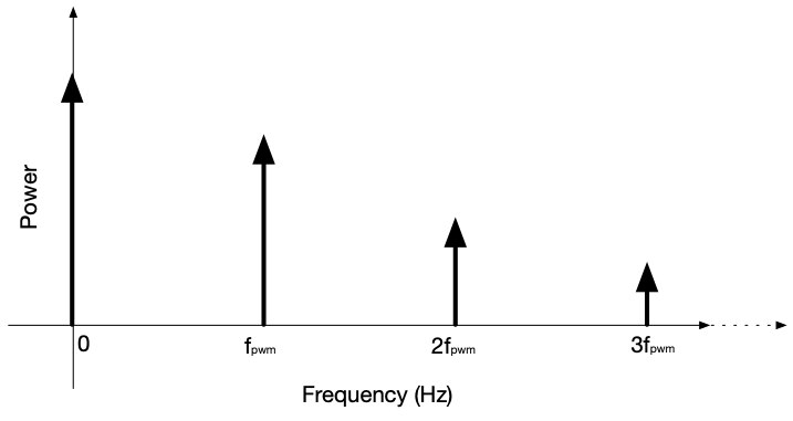
We are only interested in the low frequency components  . From the signal spectrum, as long as
  is high enough, then a simple RC filter should be effective at removing the unwanted harmonics.
The schematic for a RC low-pass filter is given below.
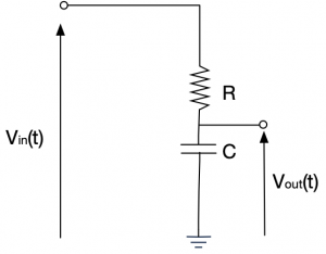
You may recall the s-plane transfer function for this circuit:

Substituting  where
where  and
and 

For the half-power point, 

Square-root both sides we get


 or
or 
This is known as the “-3dB point”. The power (for a unit load) is defined as  which can be written as
For half RMS power,

Filter Design
A single RC filter will roll off -20dB each time the frequency increased by a factor of 10 (known as a decade).
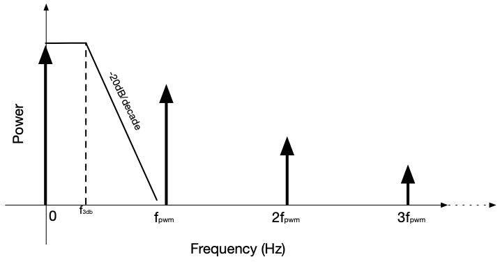
Consider the figure above. If you choose the -3dB point to be 10Hz, then the gain will be (approximately) as follows:
| Frequency (Hz) | Gain (dB) |
|---|---|
| 10 | -3 |
| 100 | -23 |
| 1k | -43 |
| 10k | -63 |
| 100k | -83 |
Alongside the resistor trays are 1nF, 10nF and 100nF capacitors. You can also open the “PWM-as-DAC” project on os.mbed.org
Digital to Analogue Conversion (DAC)
You might have noticed that using a PWM is somewhat cumbersome. Its advantage is simplicity, and particularly suited to tasks such as DC motor speed control (it is relatively simple to switch a power transistor on and off at high speed in order to drive a motor).
However, for outputting complex waveforms, such as audio or medical signals, you are advised to use a high precision and linear Digital to Analogue Converter (DAC). The micro controller you are using in these labs has an on-chip 12-bit DAC.
mbed provides an object AnalogOut which encapsulates all the necessary code to access the DAC.
#include "mbed.h"
#include “math.h"

AnalogOut  aOut(PA_5);

int main(void) {
    while (true) {
       for (float i=0.0f; i<1.0f; i+=0.01f) {
           aOut = i;
           wait(0.001f);  //approx. 1kHz
        }
    }
}