Interrupts – a first look
Although simple, polling has some major disadvantages:
- It uses a lot of CPU resource even when there are no changes in the inputs. This is unlike most modern computer systems which are event driven and can idle.
- The loop cycle time is variable (e.g. due to conditional statements). Therefore the “sampling interval” of the inputs is not constant and is said to “jitter”. This can be a problem for certain types of input signal such as audio.
- If the loop cycle is ever too long, input changes could be missed and data lost. The delay gets longer as more code is added.
- Any blocking in the loop would result in inputs being ignored. For example, we cannot easily read the terminal in the polling loop and the C-Standard
fgetsandscanfare blocking functions.
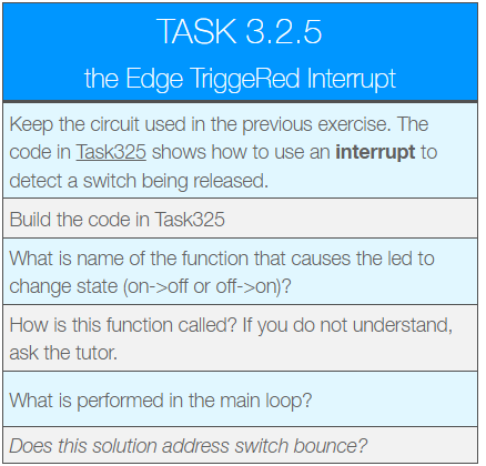
Note how the main loop simply puts the MCU in a low power sleep state. This means when there is nothing to do, the CPU does not waste cycles (and hence power). When the interrupt occurs, it wakes. This is the basis of event driven computing.
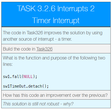
This solution is an improvement, but still does not work perfectly.
Key Points:
This solution used two types of interrupt. One is driven from the GPIO and switch, the other from an internal hardware timer.
- When a rising edge is detected, the rising-edge detection is immediately deactivated and a “one-shot” timer is started.
- The a one-shot timer (known as a
Timeout) is used to add a 200ms delay. When this time has elapsed, its own ISR is called in which the rising edge interrupt is re-enabled. - The timer is an internal device that still operates even when the CPU is in sleep mode.
The remaining problem is that a switch release sometimes registers a rising edge (due to switch bounce). In the next solution we address with with a state-machine design.
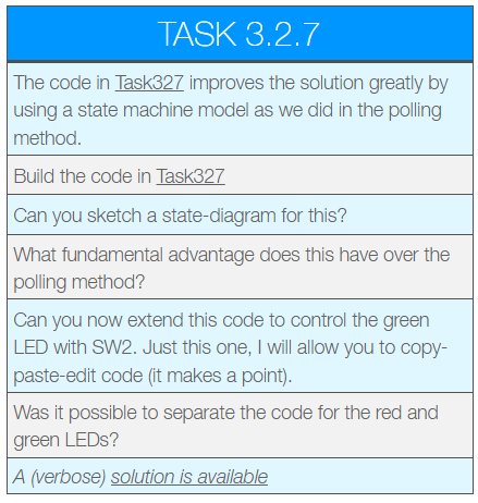
You have probably found that the two switches and LEDs don’t share any state (variables, hardware etc..), so don’t interfere with each other.
Key Points:
- In this example, it was possible to virtually duplicate code (and change some names) to add the extra switch and LED. This is because they are completely independent and share no (mutable) state.
- In general, it is not usually so simple to extend functionality. Safe interrupt code can be hard to write.
- The main routine once again just puts the MCU into a low-power sleep state. This solution is power efficient.
- All interrupt service routines are fast and short. None have any blocking calls in them, making this solution very responsive.
- Interrupts can only be preempted by higher priority interrupts. No priorities have been assigned in this code, so blocking inside an ISR could potentially delay others.
- There are many functions that should not be be called by an interrupt (such as
printf).
Race Conditions and Corruption
Interrupt service routines can be dangerous. The danger centers around “shared mutable state” – i.e. variables (but not constants) accessed from more than one interrupt.
In this section we will take a closer look at the origins of this problem.
In the previous example, the interrupt service routines (ISRs) for each switch had some global data that was shared between different ISRs. However, none of the interrupts were able to preempt each other meaning this data was always accessed exclusively.
Note – the
main()function can always be interrupted by any of the ISRs. This can often be overlooked.
Let’s now take a look under the hood of an interrupt driven application and witness data corruption. For this, we it is advised that you use the debugging facilities of Keil uVision.
Go to the source site and export for Keil uVision 5 (v5.28a or later)
https://os.mbed.com/teams/University-of-Plymouth-Stage-2-and-3/code/Task328/
To see how to export from Mbed-os to Keil uVision, watch this video (includes captions)
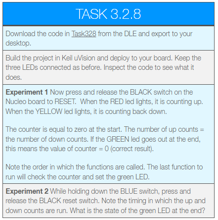
In the second experiment, you should have found that the green light stayed on. This means the final value of the counter is NOT zero!
Note – this experiment depends on timing – If it the green light went out, find the line that reads: t1.attach_us(&countDown, 15); and try tweaking the delay slightly.
The ONLY difference between the two experiments is the timing of the timer interrupt – the function of the code has NOT changed, yet the results are different.
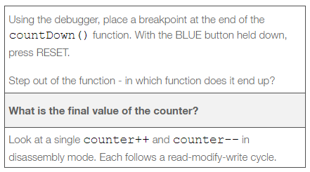
Note that counter-- requires multiple instructions and thus can be interrupted by an ISR. If an ISR interrupts this code, and itself modifies counter, then it’s stored value will become inconsistent. This is a key point for software safety.
This is the assembler for counter--
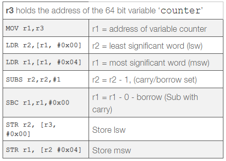
Question: When a timer interrupt occurs, many registers will be pushed to the stack, including {r0-r3}. When it returns they will be popped off again. Given this information, can you explain the final value of counter? Discuss with the tutor if not sure.
Recap – Multiple Outputs with BusOut
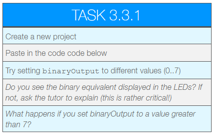
The mbed website contains a lot of useful reference and tutorial information. A great place to start is the online API guide for mbed-os. So far, we have only read from a single input pin or asserted a single output pin at a time. We often want to read groups of pins at the same time. In the next task, we are going to convert decimal numbers to binary using the LEDs as an output display.
The red LED will be the most significant bit (BIT2) and the greed LED the least significant bit (BIT0)
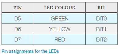
#include "mbed.h"

//lsb first
BusOut binaryOutput(D5, D6, D7);

int main() {

    //Try different values
    binaryOutput = 3;

    while (1) { }
}
BusOut
The new software component is BusOut which takes a variable number of parameters. These parameters specify (lsb first) which pins to use for the binary output. Assigning a decimal to the instance binaryOutput converts the decimal to binary, and sets the pins accordingly.
Be aware that BusOutis a convenience class. It simply maintains an internal array of DigitalOuttype objects. When you set a value (scalar integer), it sets each output in turn. This means that they do not change simultaneously. For that, you are advised to read the documentation on PortOut
Some Important Terminology
Before we move on to analogue I/O with Mbed-os, it’s important to review some important terminology:
Blocking
Where a given thread of code stops and waits for a resource to become available (such as a ADC conversion, or a network transaction), and does not proceed, we say this is blocking. Blocking is a term used in more than one context however.
Busy Wait Loop (spinning)
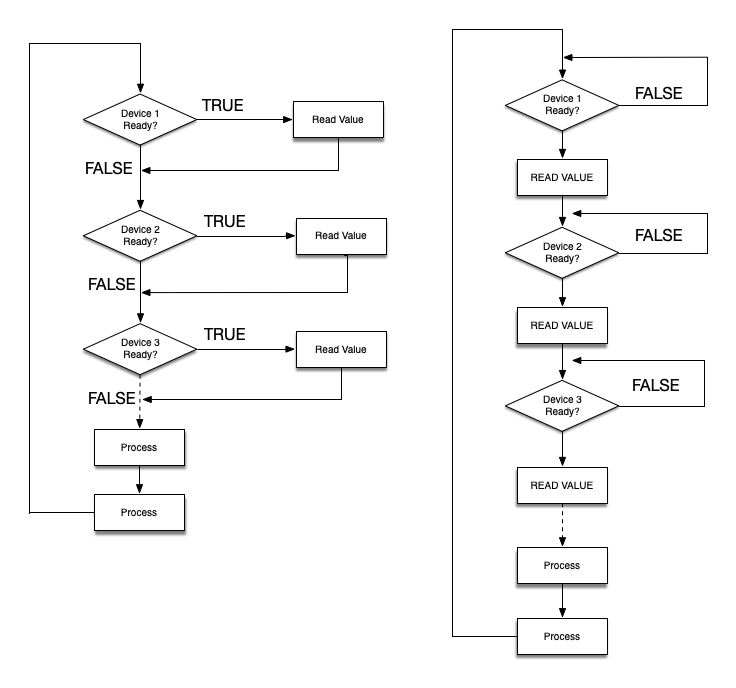
When an embedded application needs to read data from multiple sources, one method is to read each device in turn. As each device is being read, the code does not proceed until data is available before resuming. This is depicted in the figure below (right hand side).
Busy wait is considered an “anti-pattern” and is not generally recommended (but it has its place).
As a general point, busy-wait loops are not efficient in terms of CPU usage or power consumption as it can consume all the CPU time doing nothing useful. However, if all the devices are fast or have a known worst case latency, then this approach might still work and still meet all the timing deadlines / power requirements.
- One advantage is that this method (in the absence of any other concurrent task) does not risk race conditions.
- The approach also tends to promote a coding style that is very clear and simple, whereby everything is done in sequence. In terms of programming, an advantage is that this is easy to for a human to write and to follow. This point should not be neglected.
When you rapidly poll a single device in a tight loop as depicted below, this is sometimes known as “spinning”. It is usually only used when the device being waited on will finish it’s task very quickly.
In a multi-threaded environment
At risk of getting ahead of ourselves, it may be worth flagging (for future reference) that blocking in general is not always negative, and in the context of real-time operating systems (covered in level 6), this can be the right way to interface with hardware.
- It is advantageous to retain the simplicity of busy-wait, where each task is performed in sequence and to completion. This is somewhat humanistic.
- When we encounter multi-threaded programming later in the course, we discover that it is possible to block on a resource in a separate parallel thread
- This allows other functionality to continue unimpeded while blocking on a device.
- This can also be CPU and power-efficient as well. The clever part is that while it is blocking, no CPU cycles are used until the device signals (to the operating system via an interrupt) that it is ready. For this, you need something known as a scheduler and compatible device drivers.
Rapid Polling (non-blocking)
This is a technique to read data from multiple input sources without blocking and waiting for any hardware device. All we need is the (rapid) ability to check if a device is ready. This is known as polling a device (read without wait).
In the figure above (left hand side), each device is queried (polled) to see if it has any available data (or if there has been any change in status). If yes, then data is retrieved and stored. The next device is then polled.
This method does not block the current thread of execution, so all devices can be polled at high rates. It does not suffer from problems with race conditions as (in the absence of any other concurrent tasks) there is no preemption.
This method does have some disadvantages however. The loop must repeat fast enough to read all devices before any data is missed and lost. This again means CPU cycles and power are being consumed even where there is no new input to process. Furthermore, the presence of conditional statements means the execution path through the code will vary, and thus the loop timing is likely to jitter. This can cause problems where data must be read at fixed intervals.
Rapid polling is relatively complex compared to simple busy-wait code, but does not come with the risks of interrupts. Devices are rapidly polled, and then the rest of the software needs to determine (i) if anything has changed and (ii) what to update as a consequence. One strategy is to combine rapid polling with one or more state machines. In terms of power, one compromise is to slow the loop down with sleeping waits (putting the CPU into sleep states for a period of time).
Some thoughts on Interrupts
Hardware events are typically asynchronous, and interrupt are the ideal mechanism to detect an external change and react on demand. This is why modern computer systems (at the lowest level) are all ultimately driven on interrupts.
- In general, hardware interrupts are the most elegant mechanism for the CPU to respond to a hardware device in a timely way.
- As a general rule (and I’ve seen it broken!), interrupts should be kept short. This is to allow other interrupts (of equal or lower priority) to respond in a timely fashion.Interrupts can have different priorities, and if nested (we did not use this), can preempt lower priority interrupts.
Interrupts communicate through shared mutable state (global variables typically, but could be hardware device). This introduce the risk of race conditions and data corruption.
A major advantage of interrupts is that a CPU can enter a low power idle / sleep state when there are no tasks remaining. Hardware interrupts will wake the CPU when there is some useful work to be done. This is in contrast with polling methods where CPU cycles are consumed constantly.
The main disadvantage of using interrupt is scalability – as more interrupts are added, so it becomes more challenging to follow the code, optimise the priorities and to guarantee that all device response times are always honoured. There is also the issue of race conditions which should never be underestimated.
GREAT BIG WARNING (with flashing lights on it)
Note that not all functions are interrupt safe. In fact, the number of functions that may be safely used in an interrupt service routine are a minority. This includes functions such as printf, the SPI, I2C, ADC and DAC drivers in Mbed-os!
It is quite easy to write a function that is not interrupt safe. You might want to research the term reentrant function.
In short, it is all-to-easy to make a mistake with interrupts that results in a bug that may go undetected for a long time.
Later we will meet “threads” which are often considered to be a safer and more scalable alternative, and where the majority of device drivers are compatible.
Self-Study Challenge: Interrupts
You are now to solve the previous self-study task, only this time with interrupts, and safely!
Self-Directed Task
Using the same hardware as above, write a new project to do the following:
- On power up, the Green LED should flash once a second (1Hz).
- Pressing (and releasing) SW1 should reduce the flashing rate (frequency)
- Pressing (and releasing) SW2 should increase the flashing rate
- Pressing SW1 and SW2 together should reset the frequency to 1Hz
- Take steps to avoid switch bounce. You may use a
Timeror better, aTimeout. Do not usewait()
Tips:
Use one state machine per switch / timer pair. You might want to show the tutor your state-diagram before you write the code. Document this in your log book. Include any state diagrams.
You can use a Ticker to flash an LED. To change the frequency, you must detach the ticker and attach it again with the new rate.
Watch out for race conditions. Remember to temporarily turn off interrupts to protect critical sections.
Remember you can “detach” interrupt sources in mbed. A switch interrupt could detach itself and attach a Timeout. When the timeout ISR runs, it detaches itself, and reattaches the switch interrupt etc.. etc.. One approach is that each “state becomes a function”. I’ll leave you to think about that one, but I give hints when asked 😉
State diagrams can be sketched on paper, photographed with a smartphone or tablet and inserted into your logbook / notes.
You are strongly advised to complete this task before the next lab session. Remember you should spend approximately 16 hours / week on each module.