In this section, we review the subject of interfacing with the mbed-os® framework from ARM. The focus of this module is on software, written to work in modern electronic systems. In this section you will review the use / consume software components (objects) from the mbed frameworks, and later, you will learn how to create your own.
Activity 1.1 – Simple LED Circuit
In electronics, we mostly work with one (or both) of the following signals types :
Analogue – where voltages and currents can take any value, typically between and upper and lower limit
Digital – where signal voltages can only be one of two possible values
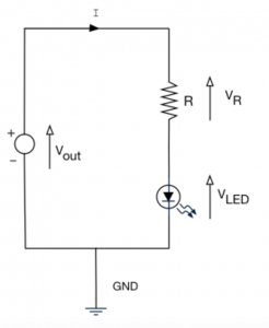
For this section, the signals are all going to be digital. Let’s start with a simple circuit schematic as shown.
All components should be mounted on the prototyping board provided, and nothing will work without a power supply!
Is obtained from the Nucleo Board.
LED Characteristics
In your kit, you are provided with three LEDs, red, green and amber. The data sheets for these devices are available. However, the most important characteristics for a clear visible brightness are as follows:
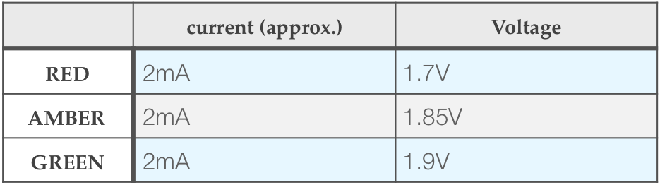
LED Voltage at 2mA
You can drive much higher currents through these LED’s but the additional perceived brightness is not significant. We want to keep current LOW for two reasons:
- The source of power for the LED will be our microcontroller. From the data sheet, the maximum output current is limited to 25mA for a single pin, up to a total maximum of 120mA for all pins.
- We want to (and should) try and save power
- There will be tolerances around these values, and they do not need to be precise.
Consider the green LED in the circuit above.
- The voltage source Vout=3.3V
- We want the current I=2mA
- For this current, from the LED data we expect VLED=1.9V
Note that +3V3 and GND are the DIGITAL power sources, not to be confused with the analogue.
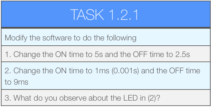
Activity 1.2 – Blinky
When learning to program a new language or framework, there are one or two traditional programs you almost always write – here is the most popular in the embedded software world, “blinky”.
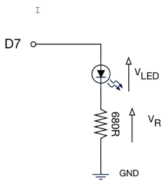
Before we write this software, first you modify the circuit.
- The figure opposite is the schematic for the blinky circuit.
- You will find the GPIO D7 labelled on the Nucleo Board.
If you we to write some code to flash the LED by referring to the microcontroller data sheet, there would be a number of things you would have to do, including:
- Set the mode of the GPIO pin (output, push/pull)
- Turn on the clock
- Set a bit somewhere in a register to set the output value
- Possibly write a for-loop to create a delay?
It’s good to know how to do this, but it’s not overly productive and will result in code written specifically for a small number of devices (or even just one device).
Using mbed Objects
Below is the source code for blinky written with mbed (task 1.2.1). Let’s break this down line by line.
//This is known as a “header file”
//In short, this copies and pastes the text file
//mbed.h into this code
#include "mbed.h"

//Create a DigitalOut “object” called myled
//Pass constant D7 as a “parameter”
DigitalOut myled(D7);

//The main function - all executable C / C++
//applications have a main function. This is
//our entry point in the software
int main() {

// ALL the code is contained in a
// “while loop”
    while(1)
	{
	//The code between the { curly braces }
	//is the code that is repeated
        myled = 1; // External LED is ON
        wait(1.0); // 1 second
        myled = 0; // LED is OFF
        wait(1.0); // External 1 second
    }
}
Firstly, consider a simple variable declaration in C, we might write something like this:
int x = 0;
The variable is called x, its data type is int (integer) and it is initialised to the value 0.
Now let’s look at one of the first lines in the Blinky code.
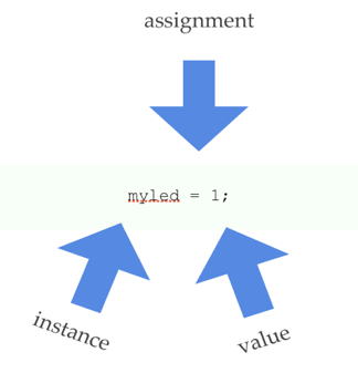
DigitalOut myled(D7);
This is the declaration and definition of the object variable myled, where the data type is DigitalOut. This is a custom data type that is included with mbed.
Note how a single parameter (the pin name) is passed. This is because when you initialise an object (a C++ concept we will meet later), you have the option to pass parameters that allow the object to initialise it’s internal state.
Note how simple the code is!
The complex details are hidden away inside the software component DigitalOut. We are using a DigitalOut component to set a pin (D7) high or low just by equating it to 1 or 0.
All the initialisation code, including write to registers to turn on the clock, set GPIO mode etc. are hidden inside the component DigitalOut
When we add an instance of this component to our application, note we are also telling it which pin it is assigned to by passing a parameter. You can create more than one instance, but each instance must use a unique pin.
In our code, we say the the object myled is an instance of type DigitalOut.
One of the great things about components is that they hide the complex details inside, again very much like an electronic component. We just have to work with its external interface. This promotes reuse and shorter / easier to write code.
Note: Consider the car as a useful analogy. You can learn to operate a car by using its interface (steering wheel, pedals and gear change stick). A car also has properties which can be monitored and sometimes changed, including:
• fuel level (read/modify)
• tyre pressure (read/modify)
• engine temperature (read only)
Details workings of a car are hidden from you. You do not need to take the engine apart to be able to drive a car. It’s hard to build a car, but relatively easy to drive one. We call this abstraction. A software component (or object) is very similar in these respects. You don’t need to see the inner workings of an object in order to use it. mbed includes a collection of very useful objects.
The mbed framework contains many such components, such that if you rebuild you code on a different board, it should just work (you might have to change the pin assignments). We say it is portable.
C++ also supports something known as operator overloading (changing the contextual meaning of +,-,= etc..). This is used extensively on Mbed to make the resulting code read more intuitively.
For level 5, we simply need to know how to use a component. Creating a component in C++ is covered in level 6 (final year).
Consider the following line.
mled = 1;
Here we simply assign an integer value to an instance of DigitalOut, and the output pin D7 changes.
Such clarity and simplicity is possible because the component understands the = operator to mean “set the pin to this value”.
That is because for DigitalOut, mbed redefines the meaning of the = operator (under the hood – more C++ magic). In level 5, we will meet a topic called “operator overloading” where you will learn to do this yourself. Done well, this results in easy to read and debug code. Done badly, and you can end up with ambiguous code!
myled.write(1);
Now consider the next line:
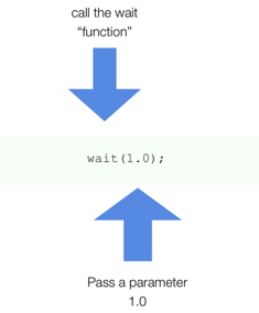
wait(1.0);
wait is one of the global utility functions in mbed. In this line of code, we are invoking a function wait. This simply delays execution for a specified time. This function is written for us (it is part of the mbed library).
wait has a single parameter. Note this time it is a fractional number. Note that when you invoke wait() in this way, the CPU can do nothing else. We say it is a blocking wait.
When your code executes a blocking operation, such as
wait(), execution pauses and does not resume until it is complete. Many functions that interact with peripheral hardware are considered to be blocking.This is because peripheral hardware is usually a lot slower than the CPU.
Note that
wait(float)is being deprecated. You should usewait_usand specify the delay in microseconds.
What we’ve written is “blinky” – the classic starter application for embedded programming.
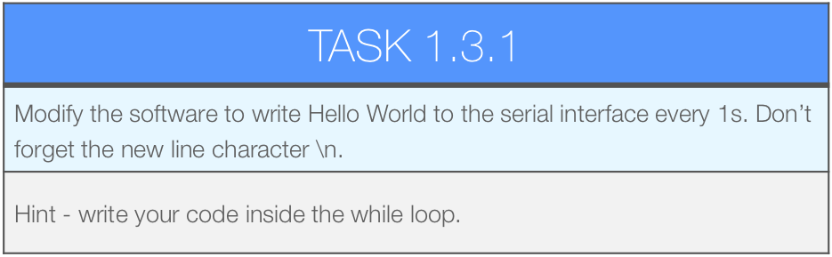
Activity 1.3 – Hello World
The other tradition is Hello World. This is normally the first program you write when learning to program on a desktop computer. However, we’re a generous lot, and wanted you to enjoy both with mbed. See the code below
#include "mbed.h"

//Create an instance of a Serial
//object called pc.
//Transmit and receive pins have pre-defined
//names USBTX and USBRX
Serial pc(USBTX, USBRX);

int main()
{

//Set the baud rate property (bits per second)
    pc.baud(9600);

    //Call the printf method on pc
    pc.printf("Hello World\n");

    //Run in an infinite loop
    while(1) {
    }
}
Note the object Serial.
Serial pc(USBTX, USBRX);
This object has a “member function” (function that acts on the data inside the object) baud which sets the speed (bits/s).
pc.baud(9600);
We say pc is special (C++) variable type, often referred to as an object. Objects are sometimes said to have “methods” or “member functions” (fancy word for functions that belong to objects). These perform specific tasks that relate to the object (they will typically update its internal state). You could compare this to a pin on a chip that performs a specific task when you pull it high or low. On doing so, a sequence of internal electronic states are updated.
Another function that Serial provides is printf.
pc.printf("Hello World\n");
The output of printf is sent to the Serial device represented by pc.
Now watch the following video
https://plymouth.cloud.panopto.eu/Panopto/Pages/Viewer.aspx?id=1f5a72c3-9458-4084-96b0-a5c9b973274f
Debugging with printf?
It is common to use printf function to debug embedded systems, and although a debugger is preferable during the development phase. It can also be invaluable for diagnostics and logging. However, it is also quite a complex function and can consume a significant amount of CPU time and memory. Have a go at the following tasks:
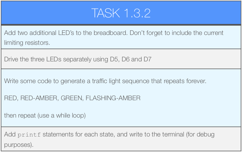
Traffic Lights
Let’s now combine what we’ve learned. In this example we will use printf to debug and trace our code.
TASK 1.3.3 HAS BEEN REMOVED
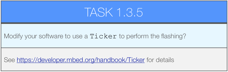
This task requires is a little different as it uses an interrupt (a topic we will cover quite soon), and you need to read the documentation and look at the example code. You should get into the habit of reading the documentation on all the mbed Classes.
Serial Input
You can also type into the terminal and read the data from the Serial Interface.
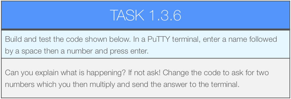
#include "mbed.h"

Serial pc(SERIAL_TX, SERIAL_RX);

int main()
{
   char nameStr[30]; // array of chars (string)
   int age;          // integer to hold your age

   pc.scanf("%s %d", nameStr, &age);
   pc.printf("Hello %s \n\r", nameStr);
   pc.printf("You are %d \n", age);
}
Question: What statements are blocking in this code? What peripheral is involved and where is it physically located?
Using Functions
You may recall C functions from previous years. Here is some revision:
#include "mbed.h"

Serial pc(SERIAL_TX, SERIAL_RX);

// array of chars (string)
char nameStr[30];
// integer to hold your age
int age;

void getData()
{
   pc.scanf("%s %d", nameStr, &age);
}

int main()
{
   getData();

   pc.printf("Hello %s \n\r", nameStr);
   pc.printf("You are %d \n", age);
}
Question: what is mean by global scope, and how does it differ from local scope?
Review
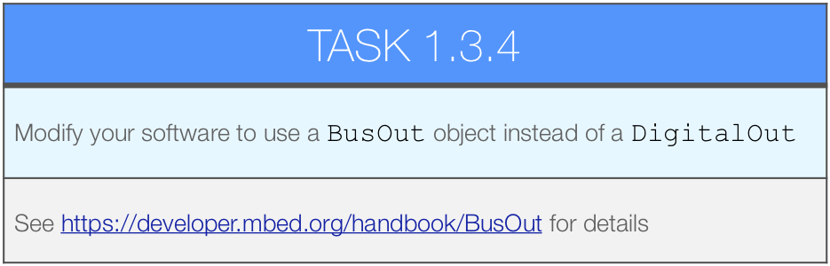
In this section, we wrote some very concise code that has only one task. There was no need for concurrency and assuming the wait() function is power-efficient, then nothing we have done is particularly wasteful of power. LEDs were controlled using General Purpose Input / Output (GPIO) using the DigitalOutput type. So we we have only considered a Digital Output.
We also used two more objects:
BusOut – for writing multiple GPIO pins
Serial – for communicating with a UART
In the next section, we add digital inputs, which brings new challenges if we still want to be power efficient and responsive.