An H-Bridge, so named due to it’s circuit topology, is a device for delivering controlling the direction of a (often large) current in one of two directions.
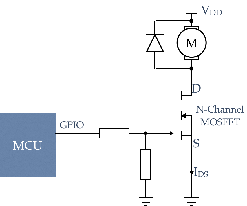
A typical application of this is the control of a DC motor. Consider the following circuit, which is used to drive a motor in a single direction:

Given that the output current of a Microcontroller is typically measured in mA, and the starting current of a DC motor is often in Amps, a transistor can be used to switch the current through the motor as shown.
- When the GPIO output is HIGH, the transistor will switch ON, and so current will flow through the motor M from VDD to ground
- When the GPIO output is LOW, the transistor will switch OFF, and so no current will flow through the motor.
In this example, a N-Channel MOSFET has been used (they tend to have lower channel resistance) but bipolar transistors can be used as well. A key observation is this:
The transistor is essential as it can switch enough current to start and run the motor
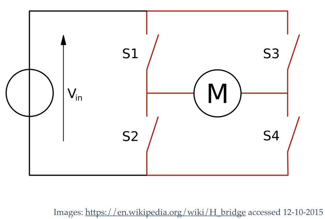
This circuit is somewhat limited however as it can only drive the motor in a single direction. To reverse the motor, imagine we could pick up the motor, rotate it by 180 degrees, and re-insert it into the circuit. Well, this is (in effect) what an H-Bridge circuit does. Let’s start with a conceptual diagram:

This circuit has 4 switches, S1, S2, S3 and S4.
- To drive the motor forward, only S1 and S4 would be closed
- To drive the motor in reverse, only S2 and S3 would be closed
- To brake, close (S1 and S3) OR (s2 and S4)
- S1 and S2 must never be closed together (short circuit)
- S3 and S4 must never be closed together (short circuit)
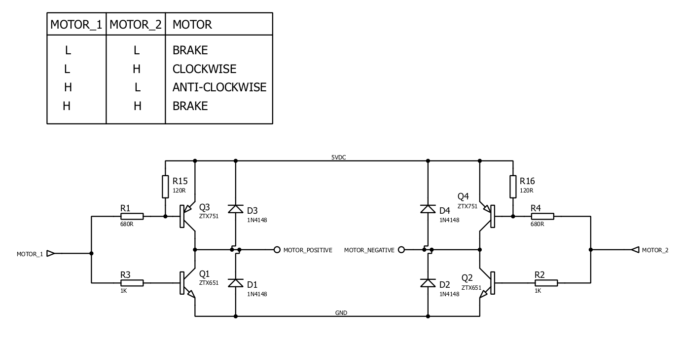
Now replace these switches with transistors, and we can control the motor using our microcontroller:

