A device that measures a bounded analogue voltage level, and encodes it in a digital integer representation.
An ADC has two key properties:
Resolution (in bits) – how many binary bits are used in the integer representation
Maximum Sampling Rate (in Hz) – the maximum number of samples than can be measure in a second.
There are other important properties, such as linearity and precision, which we will not discuss here.
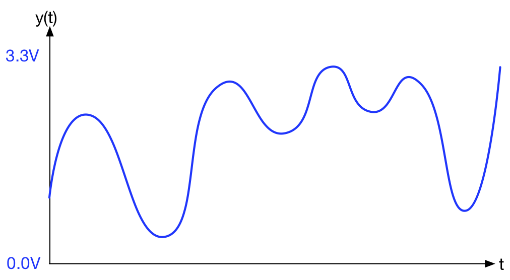
Consider the analogue waveform below:

In this diagram, we see how an analogue signal ![]() can take any value between 0.0V and 3.3V. Furthermore, you can measure the voltage at any time
can take any value between 0.0V and 3.3V. Furthermore, you can measure the voltage at any time ![]() . There are no breaks in either dimension, so we say this signal is continuous.
. There are no breaks in either dimension, so we say this signal is continuous.
In a digital computer, we may wish to record and store this waveform in the computer memory over a given time period. There are two processes that need to occur:
Sample and Hold
As ![]() is a continuous quantity, we simply cannot measure
is a continuous quantity, we simply cannot measure ![]() for all possible values of
for all possible values of ![]() . Even for a fixed duration, that would still be an infinite set of data!
. Even for a fixed duration, that would still be an infinite set of data!
Does this prove that no two infinities are the same? 🙂
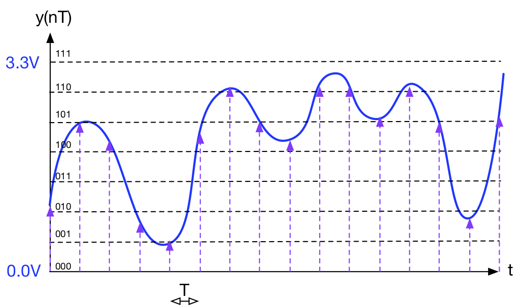
Back to earthly discussions… we need to measure a finite set of samples at regular intervals. This process is known as sampling (you can think of this as quantization along the time axis).

The first task of an Analogue to Digital Converter (ADC) is to sample and hold. A regular digital clock is used to capture and hold the voltage every ![]() seconds.
seconds.
In practice, ![]() is usually measured in
is usually measured in ![]() or
or ![]()
Information loss – At this point, you are still using analogue electronics to “hold” values. We are loosing information of course (the values between the sampling points), so we usually try to keep ![]() as small as possible. There are some mathematically derived rules to determine the minimum value of
as small as possible. There are some mathematically derived rules to determine the minimum value of ![]() . This is beyond the scope of this course, but you can read about it in any book on signal processing, or alternatively:
. This is beyond the scope of this course, but you can read about it in any book on signal processing, or alternatively:
https://en.wikipedia.org/wiki/Sampling_(signal_processing)
Quantisation
Like time ![]() , the voltage value
, the voltage value ![]() can take ANY value between two limits (0.0V and 3.3V in this case), so again, there are theoretically an infinite set of values.
can take ANY value between two limits (0.0V and 3.3V in this case), so again, there are theoretically an infinite set of values.
In a digital computer, there are no data types that can hold a value with infinite precision. ALL numbers in a digital computer are ultimately represented in binary.
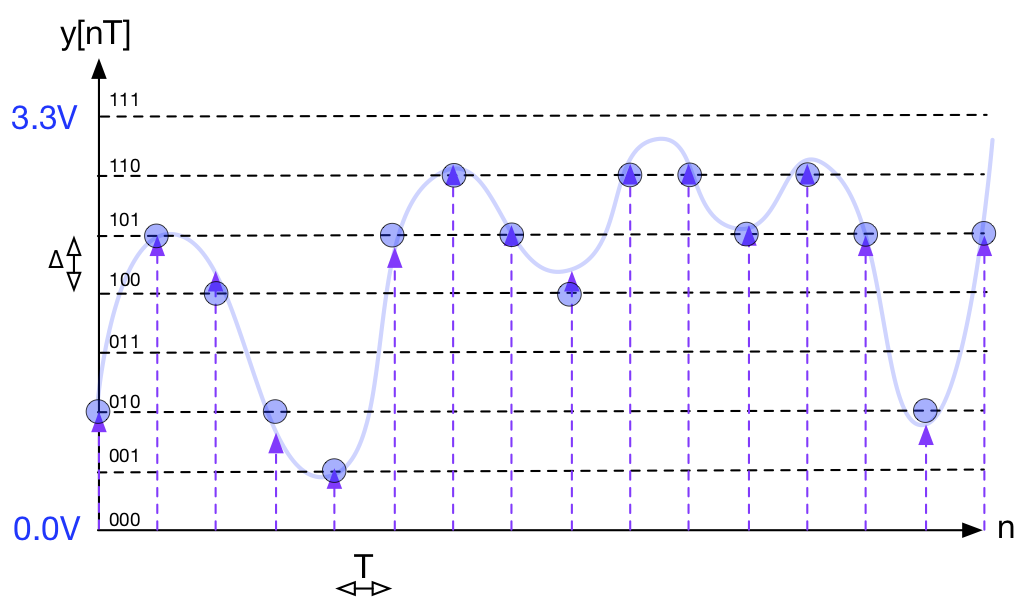
The next step is to evenly quantize along the voltage axis as shown below:

In this example I’ve used 3-bit sampling simply for clarity. The y-axis is evenly divided into 8 equal distributed values, spanning 0.0V to 3.3V.
In this example, each level is encoded as a 3-bit binary value, from 000 to 111
000 (integer 0) represents ![]()
001 (integer 1) represents ![]()
010 (integer 2) represents ![]()
![]()
111 (integer 7) represents ![]()
The process of quantisation is to consider the analogue signal being “held”, and decide which of these binary levels it is closest to (depicted by the circles). It is the nearest binary value that is presented at the output of the ADC and ultimately stored in the computer.
Quantisation noise. You will probably have noticed that there are inevitable errors. There are frequently differences between the real signal and the nearest preferred value (quantised signal). These errors manifest themselves as quantisation noise. For many real world signals (such as music), this can be random. For some signals, there may be some statistical bias in this noise.
Increasing the number of quantization levels helps to reduce this noise. To do this, we must increase the number of bits used to represent these values. This is why in music we hear about 16 bit audio (CD), 24 bit (for some recording studios) and even 32 bit when talking about sound quality. Strangely enough, increasing the sampling rate (in time) can in some circumstances, increase the signal resolution (in V), a technique known and marketed as “over-sampling” https://en.wikipedia.org/wiki/Oversampling
