Intended Learning Outcomes
- Identify the leads of an LED and light via a current limiting resistor.
- Calculate the value of a current limiting resistor given an ideal current
- Use a DVM to measure potential difference in a circuit
- Apply Kirchoffs and Ohms laws to predict voltages and currents in a simple circuit
- Use the C language to drive a single GPIO pin to a given state
Time Required: 2 weeks (8 hours lab time + self-study).
Welcome
Welcome to the start of Embedded Systems in Context, a module focused on writing “embedded software” to measure, analyse and control real-world signals and information. If you are a Plymouth student, then welcome also to the first semester on your taught programme.
This module is a first introduction to the subject of electronics, robotics and software. The focus is on software, written to work in modern electronic systems. Before we can even begin writing embedded software, it is important to have some understanding of fundamental electrical principles. Although this is taught elsewhere, it is helpful to cover the information on a needs-basis.
Activity 1.1
In electronics, we mostly work with one (or both) of the following signal types :
- Analogue – where voltages and currents can take any value, typically between and upper and lower limit
- Digital – where signal voltages can only be one of two possible values
For this section, the signals are all going to be digital. Let’s start with a simple circuit diagram, or schematic as it’s also known, as shown in Figure 1.1
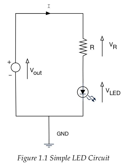
There are three components in this circuit:
- Constant Voltage Source. Think of this as the “perfect battery”. What ever the current I flowing in the circuit, the voltage across this device is ALWAYS Vout. In our circuit, this will be approximately 3.3V
- Resistor. This is used to limit the current that flows through the LED (to avoid damaging it and to save power). Resistors have a resistance property measured in Ohms (symbol
 ).
). - Light Emitting Diode (LED) – A non-linear device that emits photons of light when a current passes through it.
- Current can only flow in one direction
- Different LEDs have different characteristics.
Polarity of an LED
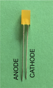
Unlike a resistor, it is important to get the LED the right way around. The current flows from anode to cathode. Virtually no current will flow from cathode to anode.
- The ANODE is the LONGER leg on the LED.
- For rounded body LEDs, a flat section on the body indicates the cathode.
Characteristics of an LED
In your kit, you are provided with three LEDs, red, green and amber. The data sheets for these devices are provided on the module site. However, the most important characteristics for a clear visible brightness are as follows:
| current (approx.) | Voltage | |
| RED | 2mA | 1.7V |
| AMBER | 2mA | 1.85V |
| GREEN | 2mA | 1.9V |
You can drive much higher currents through these LED’s but the additional perceived brightness is not significant.
We want to keep current LOW for two reasons:
- The source of power for the LED will be our microcontroller. From the data sheet, the maximum output current is limited to 25mA for a single pin, up to a total maximum of 120mA for all pins.
- We want to (and should) try to save power
- There will be tolerances around these values, and they do not need to be precise.
Assume it is the green LED in the circuit:
-
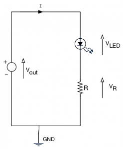
LED Circuit showing the current limiting resistor R. The voltage source

- We want
 to get a good brightness
 - For this current, from the LED data sheet we expect

Question: If
, show that the predicted value of
If you are unsure about how to answer this, check with the tutor.
Question: Given that
, and that the current
, what is the closest resister value
available in the resistor draws in the lab?
Theoretical Solution
From the previous section we calculated the resistor value as follows:
According to Kirchoff’s second law,
![]()
Therefore, we calculate ![]()
Now we know what we want ![]() to be, we can calculate
to be, we can calculate ![]() so that this condition is satisfied:
so that this condition is satisfied:
![]()
![]()
However, from our resistor stock, we had ![]() resistors, so that was chosen as the nearest value.
resistors, so that was chosen as the nearest value.
So let’s now build this circuit and measure the actual voltages with a digital voltmeter (DVM). The following shows how you wire up this circuit on a prototyping board.
Tasks
Connect your Nucleo board to the USB port of your PC, and the LED should light. We are using the 3.3V and ground (GND) pins on the Nucleo board to power this circuit.
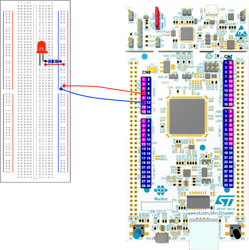
Follow this diagram carefully – note the polarity of the Digital Outputs and power lines. The resistor value is ![]() . Can you use your DVM to confirm which resistor has this value? See the glossary item for more ways to identify it. The choice of wire colour is more a convention than a rule. Please stick to this convention where possible to avoid errors.
. Can you use your DVM to confirm which resistor has this value? See the glossary item for more ways to identify it. The choice of wire colour is more a convention than a rule. Please stick to this convention where possible to avoid errors.
Task 1.1.1
Watch the following video.
| We predicted the voltages across the resistor and LED to be 1.4V and 1.9V respectively. |
| 1. Now use a digital volt meter to confirm the actual values. |
| 2. Are they the same value as the person next to you? |
| 3. Can you explain any differences? |
Activity 1.2 – Blinky
When learning to program, there are one of two traditional programs you almost always write – here is the most popular in the embedded software world, “blinky”.
Before we write this software, first you build the circuit.
- The figure below is the schematic for the blinky circuit.
- The prototype wiring is shown below.
- Watch the video – Note we are using the FZ429ZI board now, and not the F401
- See the glossary to identify the resistor value.
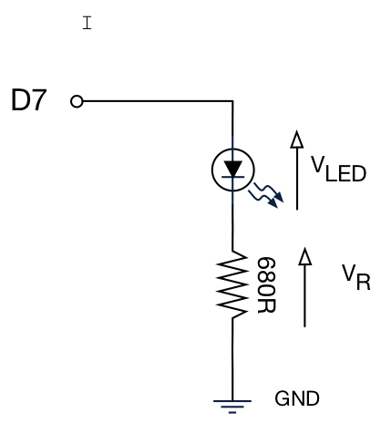
The physical connections for this schematic are shown below. Can you relate one to the other?
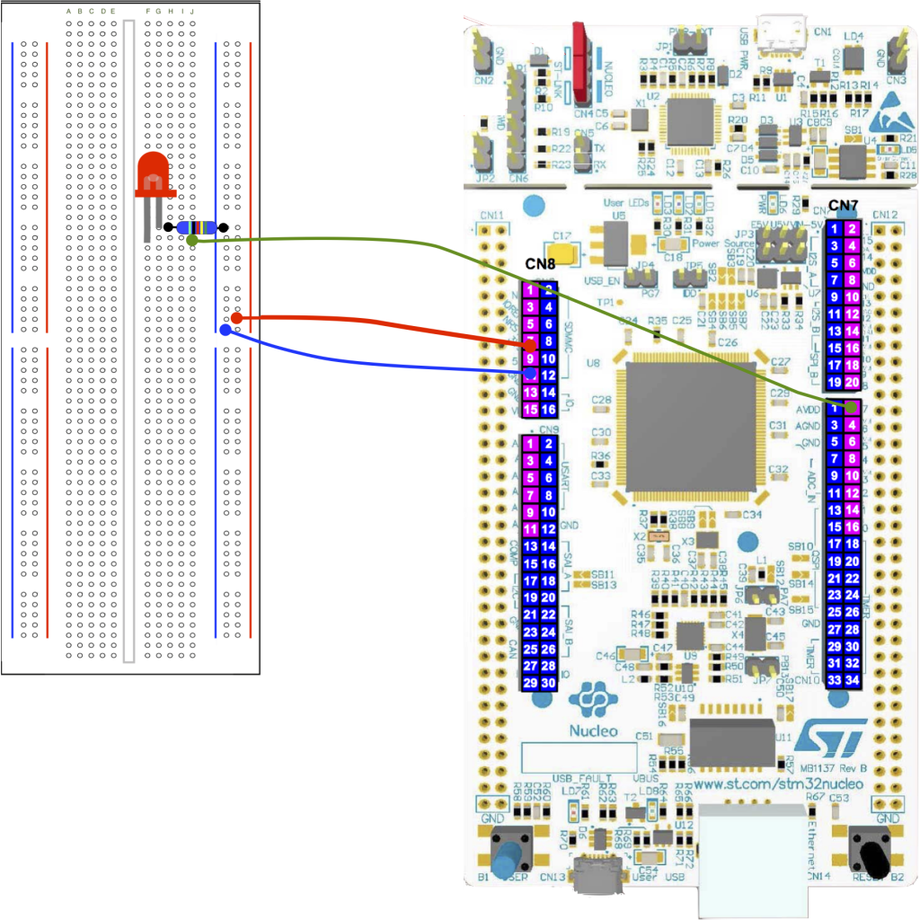
 current limiting resistor
Software
Below is the source code for blinky. Let’s break this down line by line.
//This is known as a “header file”
//In short, this copies and pastes the text file
//mbed.h into this code
#include "mbed.h"

//Create a DigitalOut “object” called myled
//Pass constant D7 as a “parameter”
DigitalOut myled(D7);

//The main function - all executable C / C++
//applications have a main function. This is
//out entry point in the software
int main() {

// ALL the code is contained in a
// “while loop”
    while(1)
	{
	//The code between the { curly braces }
	//is the code that is repeated
        myled = 1; // External LED is ON
        wait(1.0); // 1 second
        myled = 0; // LED is OFF
        wait(1.0); // External 1 second
    }
}
Firstly we have the DigitalOut “object” named “myled” (highlighted above). Think of this as a component you place in the software (as opposed to a circuit board). Some components have parameters you can use to initialize and customize them. We have one in this case.
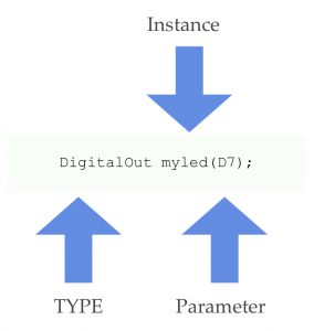
Components or “objects” contain useful functionality. We are using a DigitalOut component to set a pin (D7) high or low. When we add an instance of this component to our application, we are also telling it which pin it is assigned to by passing a parameter.
You can create more than one instance, but each instance must have a unique name so you can identify it.
In our code, we say the object myled is of an instance of type DigitalOut
One of the great things about components is that they hide the complex details inside, again very much like an electronic component. We just have to work with it’s interface. This promotes reuse and shorter / easier to write code.
Consider the following line. If we simply assign an integer value to an instance of DigitalOut, it knows to set the corresponding pin high (3.3V). This is possible because the component understands the ‘=’ operator to mean “set the pin to this value”.
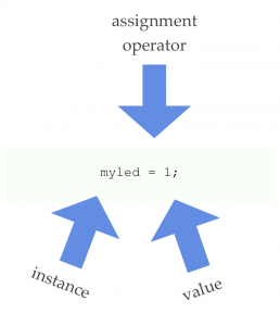
Note the semi-colon ; on the end of the line.
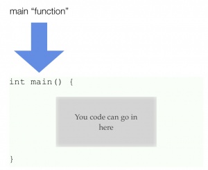
Every executable C or C++ program has a function called main. For very simple programs, this is where you will write your code. For more complex programs you will probably break your task into separate functions.
Note the code is written between the {curly parenthesis}. In embedded software, the main function rarely exits (it has nowhere to exit to!) unless you are running a multitasking operating system such as Linux.
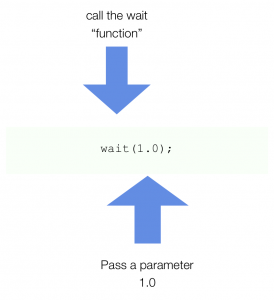
In this line of code, we are invoking a function “delay”. This simply delays execution for a specified time. This function is written for us (it is part of the Mbed library). Delay has a single parameter. Note this time it is a fractional number.
TASK 1.2.1
| Modify the software to do the following |
| 1. Change the ON time to 5s and the OFF time to 2.5s |
| 2. Change the ON time to 1ms (0.001s) and the OFF time to 9ms |
| 3. What do you observe about the LED in (2)? |
| 3. Modify the code to flash the morse-code SOS sequence (see opposite), wait for 5s, then repeat |
| In unsure, discuss with the tutor |

| Symbol | Duration (milliseconds) |
| DOT | 150ms |
| Dash | 450ms |
| Symbol space | 1 dot |
| Letter Space | 3 dots |
| Word Space | 6 dots |
Activity 1.3 – Hello World
The other tradition is Hello World. This is normally the first program you write when learning to program on a desktop computer. However, we’re a generous lot, and wanted you to enjoy both – actually we have the luxury of being able to write both. Now watch the following video:
TASK 1.3.1
| Modify the software to write Hello World to the serial interface every 1s. Don’t forget the new line character. |
| You should also use the Nucleo F429ZI board, and not the F401 as shown in the video. |
| Hint – write your code inside the while loop. |
See the glossary for a reminder about the while-loop.
#include "mbed.h"

//Create an instance of a Serial
//object called pc.
//Transmit and receive pins have pre-defined
//names USBTX and USBRX
Serial pc(USBTX, USBRX);

int main()
{

//Set the baud rate property (bits per second)
    pc.baud(9600);

    //Call the printf method on pc
    pc.printf("Hello World\n");

    //Run in an infinite loop
    while(1) {
    }
}
Task 1.3.2
| Add two additional LED’s to the breadboard. Don’t forget to include the current limiting resistors. |
| Drive the three LEDs separately using D5, D6 and D7 |
| Write some code to generate a timed traffic light sequence that repeats forever.
RED, RED-AMBER, GREEN, AMBER then repeat |
ADDITIONAL Task 1.3.3
| Modify the traffic light sequence as follows: |
| RED, RED-AMBER, GREEN, FLASHING-AMBER |
| IF you have some programming experience, try and break this into C functions. If you don’t, we will cover this later in the course. |
ADDITIONAL (ADVANCED) Task 1.3.4
Modify your software to use a BusOut object instead of a DigitalOut |
| See https://os.mbed.com/docs/v5.10/apis/busout.html for details |
Don’t worry – we’ve not covered BusOut yet, but ultimately, it is important to be able to learn from the documentation.
ADDITIONAL (ADVANCED) TASK 1.3.5
ONLY for those with previous programming experience
Modify your software to use a Ticker to perform the flashing. |
| See.https://os.mbed.com/docs/v5.10/apis/ticker.html for details |
Again – don’t worry if you can’t do this- we will cover the Ticker later in the course. However, the documentation gives some nice examples you can adapt.
ADDITIONAL TASK 1.3.6
| Build and test the code shown below. In the terminal, enter a name followed by a space then a number and press enter. Don’t worry if nothing appears on the screen as you type. The data is still being sent. |
| Can you explain what is happening? If not ask!
Change the code to ask for two numbers which you then multiply and send the answer to the terminal. |
This uses the (in)famous scanf function. So many devices use string data to communicate that at some point, you will need to learn about it (it’s introduced in this course).
#include "mbed.h"

Serial pc(SERIAL_TX, SERIAL_RX);

int main() {
    char nameString[30];
    int age;

    pc.printf("Enter your first name, then a space, then your age\n\r");
    pc.scanf("%s %d", nameString, &age);
    pc.printf("Hello %s\n\r", nameString);
    pc.printf("You are %d years old\n\r", age);

    //Loop forever
    while(1);
}
ADDITIONAL TASK 1.3.7
| The code below does the same as the previous example but the data input section has been moved to a separate function. |
Modify the code to move the output section (the two printf statements) to another function. |
Note the variables nameStr and age are now outside of all the functions. What happens if you put them inside main again? |
#include "mbed.h"

Serial pc(SERIAL_TX, SERIAL_RX);

char nameStr[30]; // array of chars (string)
int age;          // integer to hold your age

void getData()
{
   pc.scanf("%s %d", nameStr, &age);
}

int main()
{
   getData();

   pc.printf("Hello %s \n\r", nameStr);
   pc.printf("You are %d \n", age);
}
ADDITIONAL TASK 1.3.8
(for those with coding experience)
| Build the code below and test |
| What happens if the line:
is changed to
|
Modify the program such that:
|
See the glossary for more information on while loops and do-while loops
#include "mbed.h"

Serial pc(SERIAL_TX, SERIAL_RX);

char nameStr[30];
int age = 1;

void getData()
{
   pc.scanf("%s %d", nameStr, &age);
}

void printData()
{
   pc.printf("Hello %s \n\r", nameStr);
   pc.printf("You are %d \n\r", age);
}

int main()
{
   int counter = 0;
   while (age > 0)
   {
      getData();
      printData();
      counter++;
   }
   pc.printf("You entered %d names\n", counter);
   sleep();
}
ADVANCED TASK 1.3.9
Read the keyboard input and translate into morse code.
|
Setting the Pace
Ideally, you will have completed all the regular tasks (excluding those marked additional or advanced) by the end of the second week.
Feedback
If you wish to leave feedback or have a question, please use the form below.
[contact-form][contact-field label=”Name” type=”name” required=”true” /][contact-field label=”Email” type=”email” required=”true” /][contact-field label=”Website” type=”url” /][contact-field label=”Message” type=”textarea” /][/contact-form]
